
Flow system and methods for digital counting

a flow system and digital counting technology, applied in fluid controllers, laboratory glassware, instruments, etc., can solve the problems of inability to carry out digital techniques, analysis ends, and digital techniques can be relatively complex, and achieve the effect of reducing the evaporation of each nano-to-attoliter dropl

Active Publication Date: 2018-03-08
SELMA DIAGNOSTICS APS
View PDF5 Cites 8 Cited by
  • Summary
  • Abstract
  • Description
  • Claims
  • Application Information

AI Technical Summary

Benefits of technology

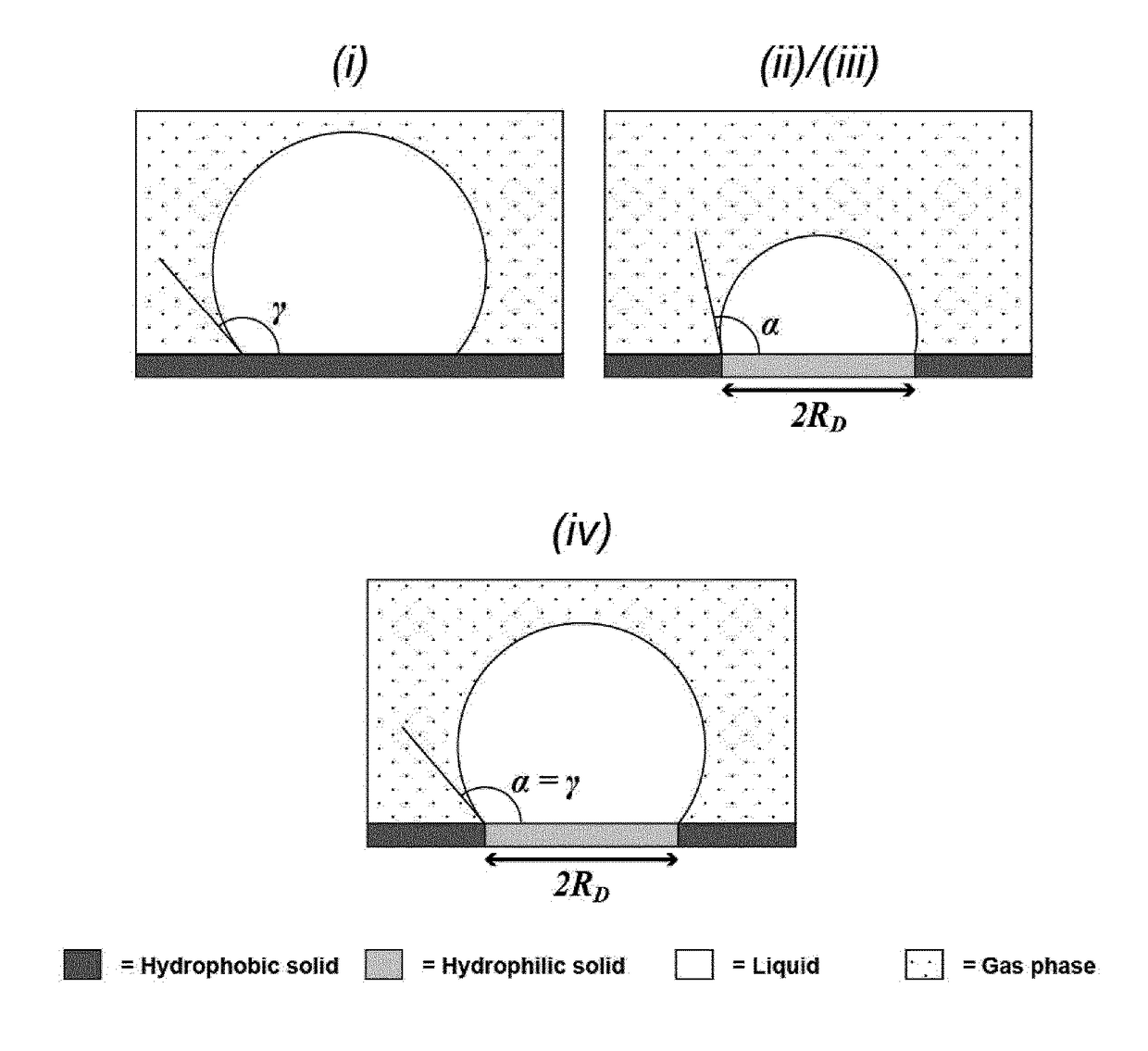
The present invention provides a method for capturing analytes on a hydrophilic surface using a linker molecule, which connects the capture probe to the surface. The capture probe can be specific to a particular analyte type and can be arranged in different regions on the surface. The method allows for multiple analyte types to be captured and organized specifically on the surface, and the captured analytes can be removed and re-introduced to the flow system for further analysis. The method also allows for repeated measurement and improved signal-to-noise ratio. The capture probe can be an oligonucleotide, protein, peptide, or synthetic variant thereof, and different types of capture probes can be used in combination to capture different analyte types. The method can be used in dPCR and micro-colloid assisted dELISA.

Problems solved by technology

However, digital techniques can be relatively complex, in part due to the technical difficulty in isolating and manipulating single molecules.
These tiny volumes can create challenges because the fluid dynamics of small volumes present behaviors, at typical laboratory temperature and pressure that make processing difficult.
A major challenge inherent in both of these array types is the way that they are loaded with sample and accessory reagents.
This problem is absent from capillary arrays, because each compartment has two openings, such that if the liquid sample is added from the top opening, then air can escape through the bottom opening.
However, when it comes to exchanging the liquid held within the micro-well or capillary compartments with another liquid, an additional issue arises, which is caused by the slow diffusion of molecules.
However, all three types of micro-compartmentalization formats (micro-well, capillary and surface tension arrays) are facing the challenge of preserving a large number of liquid micro-droplets for a sufficient long time in order to allow digital counting to be conducted.
Once evaporated, the ability to process the molecule within the microdroplet is gone, the digital technique cannot be carried out.
In this way, the content of individual compartments cannot evaporate and neighboring compartments cannot exchange their content, which would otherwise lead to cross-contamination.
The disadvantage of having a physical seal is that once the compartments have been sealed off, the analysis ends, because the lid cannot be easily removed without disrupting the integrity of the micro-compartments.
Furthermore, to apply a physical seal, the compartments have to be structured as micro-wells / -cavities / -recesses, which, due to slow molecular diffusion, results in technical difficulties with exchanging the liquid in the compartments during the initial preparative steps.
However, one of the disadvantages of a chemical seal is that analytes or other biomolecules from the sample may partition into the non-polar phase and lead to (i) sample loss and / or (ii) inter-droplet contamination.
Even further, when a bulk aqueous phase is displaced by a bulk oil phase or vice versa there is a risk of producing emulsion droplets, i.e. micron-sized inclusions of water in oil or vice versa.
Emulsion droplets may constitute an experimental nuisance, since they can foul the surfaces and / or deteriorate the flow-performance of the device.

Method used


Image

  • Flow system and methods for digital counting
  • Flow system and methods for digital counting
  • Flow system and methods for digital counting

Examples


example 1

Formation and Preservation of a Femtoliter Aqueous Microdroplet Array

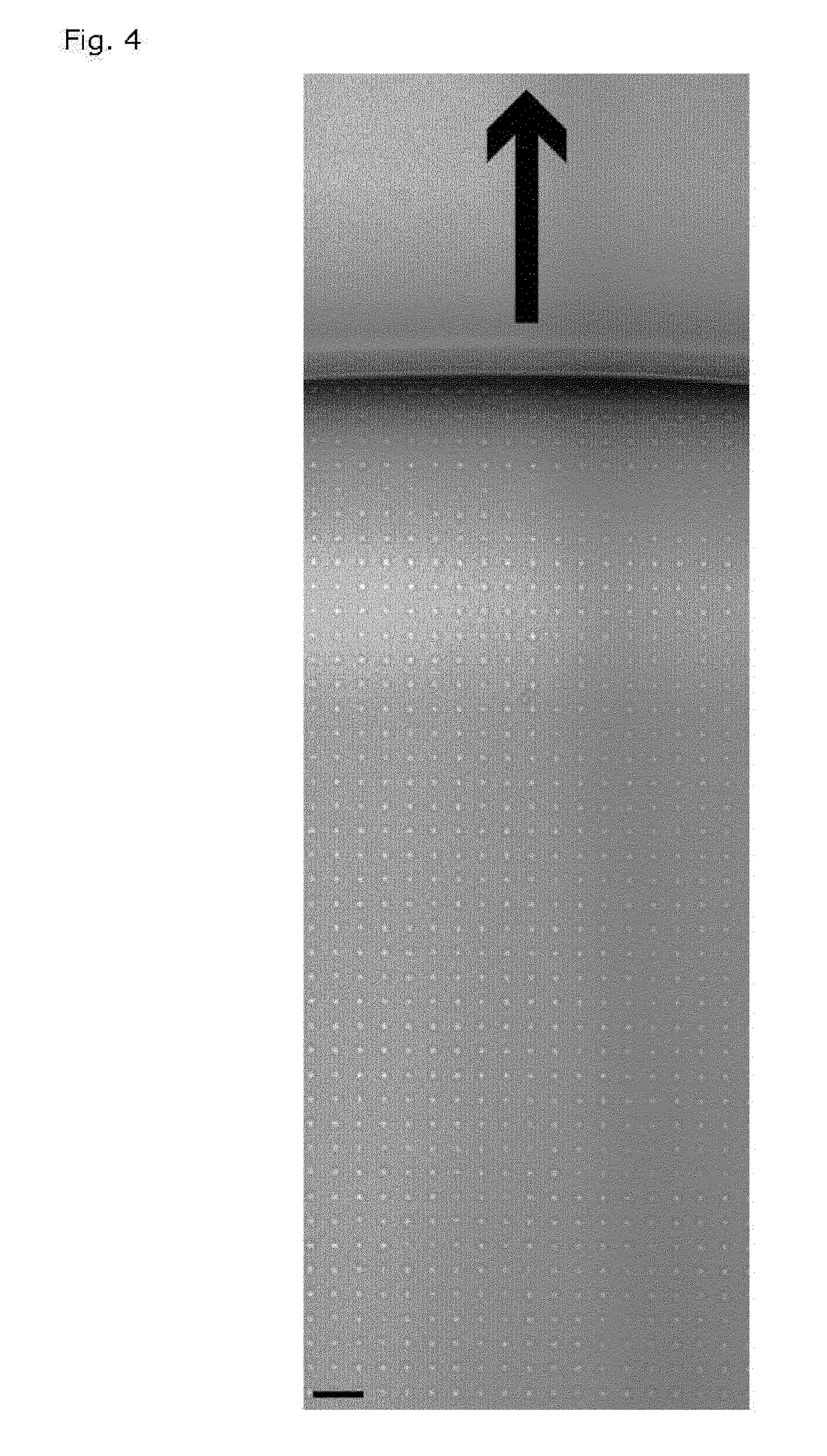
[0320]To form stable microdroplets, a regular quadratic array of hydrophilic circular features embedded on a planar hydrophobic region was contacted with a phosphate buffered aqueous solution. A 10 μl plug of the solution was actuated across the surface of the array, thus leaving microdroplets behind on the hydrophilic features as shown on the micrograph in FIG. 4.

[0321]The flow system was defined by two openings at each end of a rectangular channel to guide the liquid. The width of the channel was 3 mm, the length was 16 mm and the height was 150 μm. The array was placed centrally in the channel, with a width of 2.9 mm, a length of 14 mm and comprised a total of 406,000 hydrophilic features. The diameter of the hydrophilic circles was 5 μm, and the intercircle spacing was 10 μm. The contact angle of the aqueous solution on the hydrophobic surface was approx. 110 degrees and the experiment was conducted at ambient ...

example 2

How to Render an Array of Aqueous Micro-Droplets Evaporation-Resistant by Optimizing Flowchannel-, Droplet- and Array-Geometry

[0323]Consider a flow channel in which a chemically patterned solid substrate has been embedded. The chemical pattern consists of circular hydrophilic regions organized into an array. The hydrophilic array is surrounded by a continuous hydrophobic region. In this way, an array of microdroplets is formed on top of the hydrophilic features once an aqueous solution is infused and subsequently withdrawn from the flowchannel, as illustrated in Example 1.

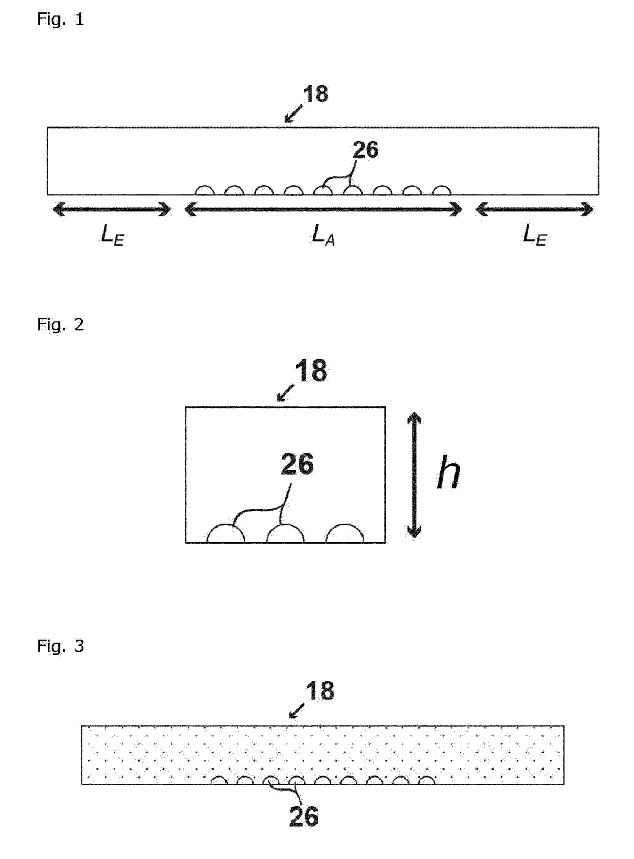
[0324]The dimensions of the flow channel are defined on FIG. 13, and are characterized by h, which is the height of the channel, lA, which is the length of the flowchannel covered by the array, lE, which is the length of the excess part of the channel leading to the inlet / outlet, but not hosting the array. The parameters defining the array are the droplet radius RD, defined as the radius of the hydrophilic feature ...

example 3

Fabrication of a Flow System

[0333]Fabrication of a flow system took place in two main steps; one step utilizes UV photolithography and microfabrication processing to produce the patterned hydrophilic features, whereas the second step deals with integrating the hydrophilic pattern into a flow compartment exhibiting the right geometry. Below both steps will be described in more detail.

[0334]Microfabrication of a Patterned Hydrophilic Substrate.

[0335]In this embodiment of the invention, the hydrophilic features were composed of quartz (SiO2) and the hydrophobic region was composed of perfluorodecyltrichlorosilane (FDTS). In the first step of the fabrication process, a molecular monolayer of FDTS was deposited on the quartz wafer by molecular vapor deposition using an MVD 100 Molecular Vapor Deposition system (Applied Microstructures Inc.). The FDTS underwent covalent attachment to silanol groups on the surface of the quartz and hence produced a hydrophobic monolayer on the wafer surfac...


PUM

PropertyMeasurementUnit
heightaaaaaaaaaa
droplet radiusaaaaaaaaaa
temperatureaaaaaaaaaa

Abstract

The present invention relates to methods and systems for testing for the presence of a material such as one or more analyte types within a sample and more particularly, for improved single enzyme-linked immunosorbent assay (sELISA) testing as well as other variants of single-enzyme linked molecular analysis (SELMA). The invention involves flow systems for digital counting of analytes with at least one opening (inlet / outlet). A support with hydrophilic and hydrophobic patches preferably harbours capture probes immobilised on the hydrophilic features. Nano-to-attoliter droplets are formed on the hydrophilic features. A gas phase (called gas phase seal) is applied to prevent / reduce evaporation from the droplets.

Description

FIELD OF THE INVENTION[0001]The present invention relates to methods and systems for testing for the presence of a material such as one or more analyte types within a sample and more particularly, for improved single enzyme-linked immunosorbent assay (sELISA) testing as well as other variants of single-enzyme linked molecular analysis (SELMA).BACKGROUND OF THE INVENTION[0002]Scientists are developing techniques for analyzing changes in biological and chemical systems, where these changes often relate to the switching between two or more states. For example, Witters et al. in Digital Biology and Chemistry (DOI: 10.1039 / C4LC00248B, (Frontier) Lab on a Chip, 2014, 14, pp. 3225-3232) discuss the development of various digital biological and chemical technologies. These digital technologies can work quite well, as digital techniques offer advantages in terms of robustness, assay design, and simplicity because quantitative information can be obtained with qualitative measurements. However...

Claims


Application Information

Patent Timeline
Patent Type & Authority Applications(United States)
IPC IPC(8): G01N33/543G01N33/52B01L3/00G06M11/00
CPCG01N33/54386G01N33/521B01L3/5088G06M11/00G01N33/54366B01L3/502B01L2200/142B01L2300/0636B01L2300/0816B01L2300/0819B01L2300/0877B01L2300/089B01L2300/165B01L2400/049
Inventor KUNDING, ANDREAS HJARNE
Owner SELMA DIAGNOSTICS APS
Learn More