Electrically conductive adhesive agent composition, and electrically conductive adhesive film and dicing-die-bonding film using the same

Active Publication Date: 2018-12-06
FURUKAWA ELECTRIC CO LTD
View PDF8 Cites 6 Cited by
  • Summary
  • Abstract
  • Description
  • Claims
  • Application Information

AI Technical Summary

Benefits of technology

The present patent aims to provide an electrically conductive adhesive agent composition that can be used as a bonding material for bonding semiconductor chips onto lead frames or circuit electrode parts of insulating substrates. The composition comprises a metal particle and a prescribed organophosphorus compound, which can form a lead-free bonding layer with great heat resistance and mounting reliability. The patent also provides an electrically conductive adhesive film and a dicing-die bonding film that utilize this composition.

Problems solved by technology

However, hazardousness of lead has become a problem in recent years, and there is an increasing demand for lead-free bonding materials.
However, since such Au-based alloy materials which contain a noble metal are expensive, and since expensive high-temperature vacuum reflow machines are necessary for attaining higher mounting reliability, Au-based alloy materials are not yet in practical use.
Also, there is a problem such that many lead-free solders have poor wettability compared with lead solders.
Due to this poor wettability, there is a higher risk that the solder will not wet over the die pad part and that bonding defects such as insufficient soldering will occur when using a lead-free solder as a bonding material.
Since the problem of wettability particularly tends to become worse as the melting point of a lead-free solder increases, it was difficult to attain both heat resistance and mounting reliability at the same time.
Since these diffusion sintering-type solders have a low melting point in a state before sintering and the mounting temperature can therefore be reduced, and since diffusion sintering-type solders will irreversibly have a high melting point in a state after the diffusion sintering reaction, diffusion sintering-type solders are expected to attain both heat resistance and mounting reliability at the same time, which was difficult with conventional lead-free solders.
However, since diffusion sintering-type solders also have the problems of wettability as with conventional lead-free solders, the risk of insufficient soldering cannot be avoided when bonding a large surface area.
Also, since diffusion sintering-type solders in a state of a sintered body are hard and brittle, there are problems of poor stress relaxation properties and low thermal fatigue resistance.
Sufficient bonding reliability therefore has not yet been attained.
However, these flux components easily absorb moisture and easily bleed out, and the absorbed moisture and the bleed-out are known to adversely affect the reflow resistance reliability (MSL) after moisture absorption in a sealed semiconductor element package.
Flux is therefore generally washed off after the solder reflow mounting, but said treatment has problems of consuming time and the treatment of the washing wastewater.
On the other hand, reduction of the added amount of the flux component, such as a carboxylic acid or an alcohol, that causes moisture absorption and bleed-out so as to avoid the aforementioned problems will cause another problem such that removing capability of the oxide film becomes poor and that sufficient electrical conductivity and other properties cannot be exerted.
The problems therefore have not yet been fully solved.

Method used


Image

  • Electrically conductive adhesive agent composition, and electrically conductive adhesive film and dicing-die-bonding film using the same
  • Electrically conductive adhesive agent composition, and electrically conductive adhesive film and dicing-die-bonding film using the same
  • Electrically conductive adhesive agent composition, and electrically conductive adhesive film and dicing-die-bonding film using the same

Examples


examples

[0093]The present disclosure will be further explained in detail below based on examples. However, the present disclosure is not limited by the examples.

[0094]

[0095]Abbreviations for the raw materials used are as follows.

[Metal Particles (Q)]

[0096]Mixture obtained by mixing the first metal particle (Q1) with the second metal particle (Q2) in a mass ratio of 2:1

[0097]First Metal Particle (Q1)

[0098]Cu particle: fine copper powder, a product of Mitsui Mining & Smelting Co., Ltd., average particle size (D50): 5 μm

[0099]Second Metal Particle (Q2)

[0100]SnBi alloy particle: fine solder powder (Sn72Bi25), a product of Mitsui Mining & Smelting Co., Ltd., average particle size (D50): 7 μm

[0101]The average particle size (D50) of the metal particles was measured by a laser diffractometer (SALD-3100, product of Shimadzu Corp.).

[0102][Resin (M)]

[0103]Maleimide Resin

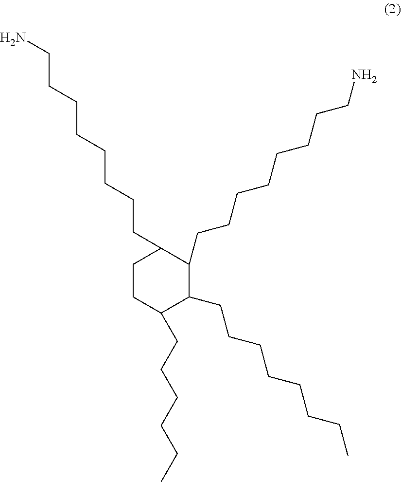
[0104]Mixture obtained by mixing BMI-3000 with, as a polymerization initiator, Perbutyl® O in a mass ratio of 100:5

[0105]BMI-3000: Bi...

examples 1 to 4

[0129]In Examples 1 to 4, electrically conductive adhesive agent compositions were obtained by mixing the materials shown in Table 1, among the aforementioned materials, so that the proportion of the metal particle (Q) would be 93.7% by mass, the proportion of the resin (M) would be 4.5% by mass, and the proportion of the flux would be 1.8% by mass.


PUM

PropertyMeasurementUnit
Temperatureaaaaaaaaaa
Electrical conductivityaaaaaaaaaa
Molecular weightaaaaaaaaaa

Abstract

The electrically conductive adhesive agent composition comprises a metal particle (Q) and a prescribed organophosphorus compound (A), and the metal particle (Q) comprises a first metal particle (Q1) made of a single metal selected from the group of copper, nickel, aluminum and tin or an alloy comprising two or more metals selected from said group.

Description

CROSS REFERENCE TO RELATED APPLICATIONS[0001]The present application is a continuation application of International Patent Application No. PCT / JP2016 / 087662 filed on Dec. 16, 2016, which claims priority to Japanese Patent Application No. 2016-023614, filed on Feb. 10, 2016. The contents of these applications are incorporated herein by reference in their entirety.BACKGROUNDTechnical Field[0002]The present disclosure relates to an electrically conductive adhesive agent composition, and an electrically conductive adhesive film and a dicing-die bonding film using the same.Background Art[0003]In general, a semiconductor device is produced by a step of forming a die mounting material for bonding a semiconductor element (chip) onto an element-supporting part of a lead frame or onto a circuit electrode part of an insulating substrate, a step of mounting the semiconductor element onto the surface of the die mounting material on the lead frame or the circuit electrode to bond the semiconducto...

Claims


Application Information

Patent Timeline
IPC IPC(8): C09J9/02H01L21/683H01L23/00C09J11/06C09J7/35C09J7/10
CPCC09J9/02H01L21/6836H01L24/29C09J11/06C09J7/35H01L21/78H01L2224/73265H01L2224/83191H01L2224/92247H01L2924/181H01L24/73H01L24/83H01L24/92H01L2224/2929H01L2224/29347H01L2224/29355H01L2224/29324H01L2224/29311C09J2400/16C09J2205/102C09J2203/326C09J2479/08C09J157/12C09J201/00H01B1/22H01L2224/48247H01L2224/48465C09J7/10C09J11/02C08K3/08C09J2461/00C09J2463/00C09J179/08C08K5/50C09J2301/314C09J2301/304C09J2301/408H01L2924/00012H01L2924/00C09J7/20C09J11/04C09J201/025H01L21/56C09J163/00
Inventor SATO, SHUNICHIROMIHARA, NAOAKISUGIYAMA, JIROU
Owner FURUKAWA ELECTRIC CO LTD
Why Eureka
Try Eureka