
A turbine engine part coated in a thermal barrier, and a method of obtaining it

Active Publication Date: 2019-08-22
CENT NAT DE LA RECHERCHE SCI +3
View PDF0 Cites 4 Cited by
  • Summary
  • Abstract
  • Description
  • Claims
  • Application Information

AI Technical Summary

Benefits of technology

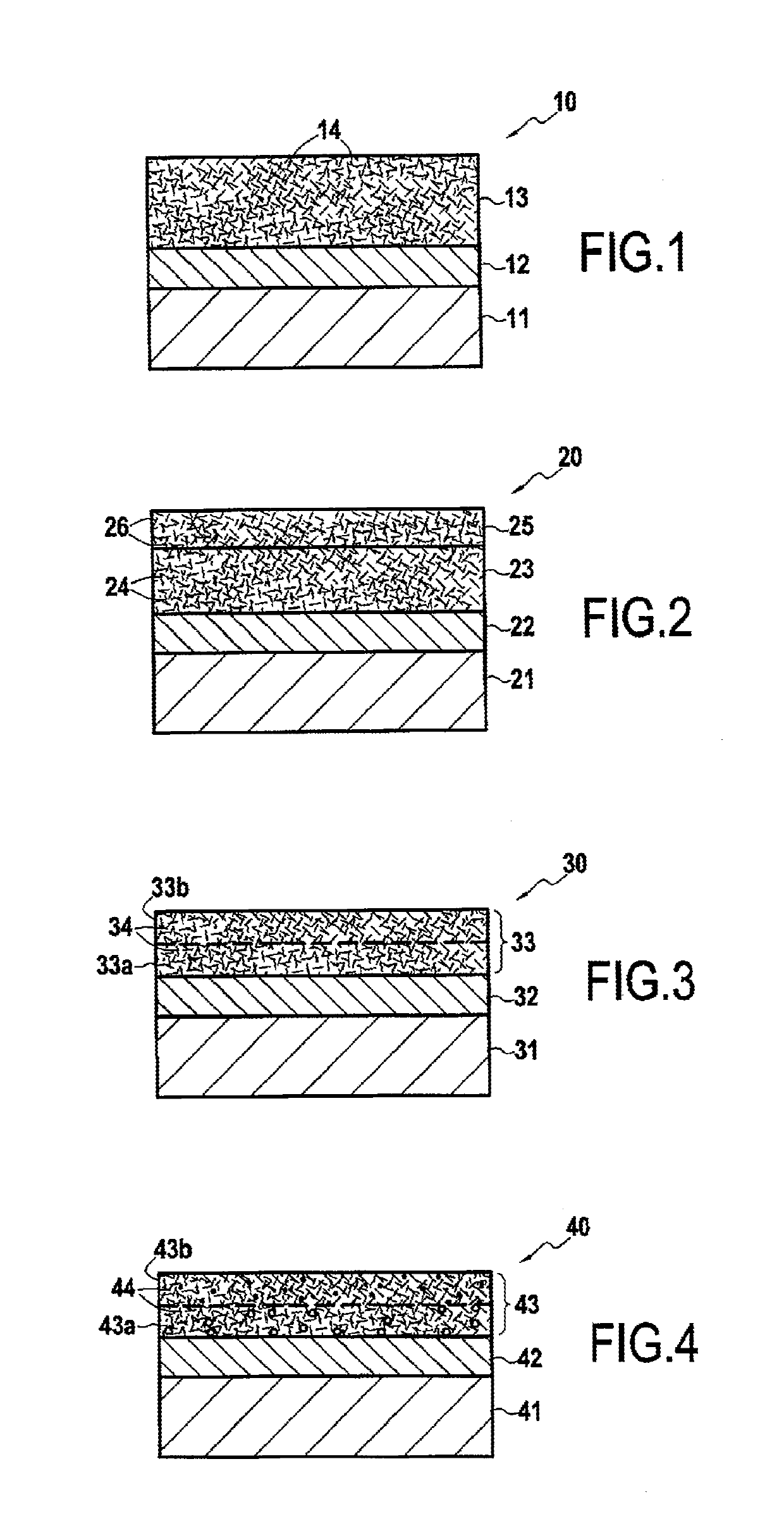
The present invention relates to a new coating system for turbine engine parts that helps to protect against damage from CMAS compounds (calcium and magnesium aluminosilicates) and maintains mechanical strength. The coating system consists of two layers: a first ceramic layer with reinforcement fibers and a second ceramic layer with additional protection against CMAS compounds. The first layer acts as a thermal barrier and is porous to allow for limited infiltration by CMAS compounds, while the second layer provides more effective protection against CMAS compounds. The patent text also describes alternative methods for preparing the coating system that can be combined to achieve desired results.

Problems solved by technology

Parts present in the hot portions of an aviation turbine engine that is operated in a desert environment or in surroundings that are very polluted, become degraded quickly because of damage from sand and from alkaline compounds present in the air ingested by the engine.
Those two mechanisms diminish the mechanical properties of the thermal barrier and can lead to it cracking during stages in which the engine is cooling.
Furthermore, the ingestion of solid particles leads to phenomena of the thermal barrier being eroded, which barrier then spalls so as to leave the underlying substrate bare, thereby reducing the lifetime of the parts.

Method used


Image

  • A turbine engine part coated in a thermal barrier, and a method of obtaining it
  • A turbine engine part coated in a thermal barrier, and a method of obtaining it

Examples


example

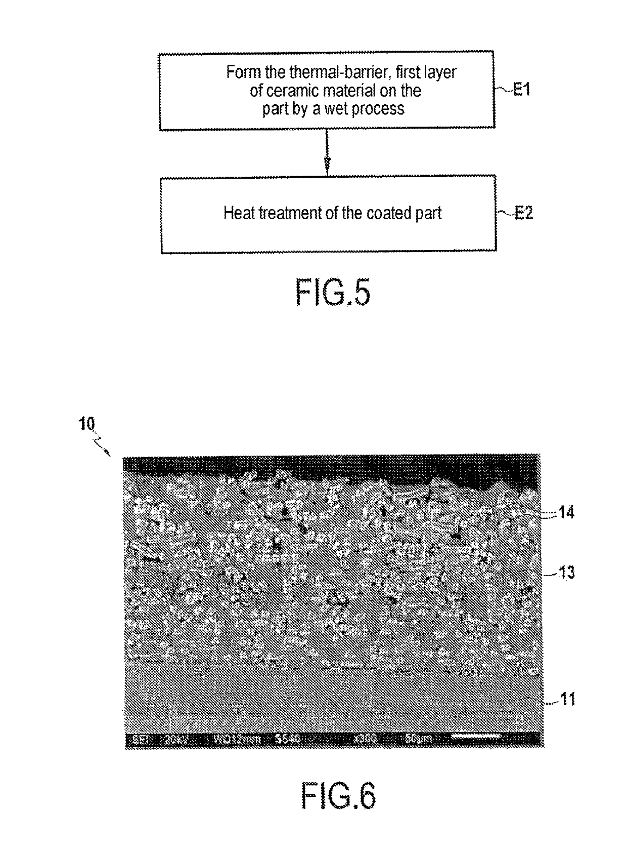
[0047]A method has been performed on a turbine engine part made of nickel-based superalloy (type AM1) covered in a bonding underlayer of NiPtAl type. In this example, the object was to obtain a thermal-barrier, first layer comprising an yttria stabilized zirconia matrix having first ceramic fibers made of yttria stabilized zirconia dispersed therein.

[0048]In known manner, a first bath was initially prepared in order to obtain a YSZ sol comprising 7.08 milliliters (mL) of 1-propanol, 0.88 mL of acetyl acetone, 4.93 mL of zirconium propoxide, and 2.36 mL of yttrium nitrate.

[0049]Thereafter, a second bath was prepared for use subsequently to dip-coat the part with the thermal-barrier, first layer filled with ceramic fibers. The second bath comprised 1-propanol and a dispersing agent of PVP 3500 type at 1%, to which there was added the commercial YSZ powder sold under the name Tosoh TZ6Y, and YSZ ceramic fibers sold by the supplier Zircar Zirconia. In the solid portion of the second bat...


PUM

PropertyMeasurementUnit
Fractionaaaaaaaaaa
Fractionaaaaaaaaaa
Fractionaaaaaaaaaa

Abstract

A turbine engine part coated in at least a first ceramic layer forming a thermal barrier and including a ceramic material with first ceramic fibers dispersed in the first layer. The first layer may have a chemical composition gradient between a material for forming a thermal barrier and a material for providing protection against calcium and magnesium aluminosilicates, which is present at a greater content in an outer zone of the first layer, and / or the first layer may be porous and may present a porosity gradient such that an outer portion of the first layer presents lower porosity.

Description

BACKGROUND OF THE INVENTION[0001]The present invention relates to the general field of thermal barrier coatings used for thermally insulating parts in high-temperature environments. The invention applies more particularly to the thermal barriers used for protecting parts made of superalloys or out of ceramic matrix composite material in aviation gas turbines.[0002]Parts present in the hot portions of an aviation turbine engine that is operated in a desert environment or in surroundings that are very polluted, become degraded quickly because of damage from sand and from alkaline compounds present in the air ingested by the engine. These compounds, known as calcium and magnesium aluminosilicates (CMAS) and comprising in particular oxides of calcium, of magnesium, of aluminum, and of silicon, can degrade the coating that provides a thermal barrier and that covers certain parts in hot portions of a turbine engine.[0003]Among the mechanisms whereby CMAS compounds degrade the thermal barr...

Claims


Application Information

Patent Timeline
IPC IPC(8): C23C28/00C23C14/08C23C4/10C04B41/52B64C11/20
CPCC23C28/321C23C14/083C23C4/10C04B41/52B64C11/205F05D2300/6033F23R2900/00018C04B41/87C04B41/89C04B41/009C04B41/5042C04B2111/00405C25D13/02C23C18/1216C23C18/1225C23C18/1241C23C18/1254C23C18/127C23C18/1283F01D5/288F05D2300/614C04B35/80C04B41/4535C04B41/4596C04B41/4527C04B41/5096C04B41/4537C04B41/4539C04B41/4582C04B41/5045C04B41/522C23C28/00F01D5/28C04B38/0051C04B2235/522C04B2235/526
Inventor JOULIA, AURÉLIENMALIE, ANDRÉ HUBERT LOUISANSART, FLORENCEDELON, ELODIE MARIEDULUARD, SANDRINE
Owner CENT NAT DE LA RECHERCHE SCI
Learn More