
Reconfigurable Implantable Medical System For Ultrasonic Power Control And Telemetry

a medical system and ultrasonic power technology, applied in the field of reconfigurable implantable medical systems for ultrasonic power control and telemetry, can solve the problems of increasing the input voltage of the system not always the best strategy to recharge the capacitor faster, health hazards can arise, and the charging process can be very slow, so as to limit the amount of energy

Active Publication Date: 2019-10-17
NORTHEASTERN UNIV
View PDF0 Cites 5 Cited by
  • Summary
  • Abstract
  • Description
  • Claims
  • Application Information

AI Technical Summary

Benefits of technology

The patent describes a system and method for controlling ultrasonic power and telemetry in an implantable device. The system includes a charging device and an implantable device that communicate wirelessly through the body. The implantable device has an ultrasonic transducer that receives the charging signal and a power unit that harvests energy from the charging signal. The harvested energy powers a sensing or actuation unit, which can read data from the implantable device and transmit it through the ultrasonic transducer. The system can adapt the ultrasonic transmission operations, data processing operations, and sensing operations based on the energy harvested from the charging signal. The technical effects of this system include improved ultrasonic power control and telemetry in an implantable device.

Problems solved by technology

Powering implanted electronic systems is a critical challenge in the area of implantable medical devices (IMDs) [A1] [A2].
Clearly, this is a crucial problem especially for life-saving medical devices like cardiac or neural bio-implants.
In specific cases, depending on the power of the acoustic wave and the duration of the exposure, health hazards can arise.
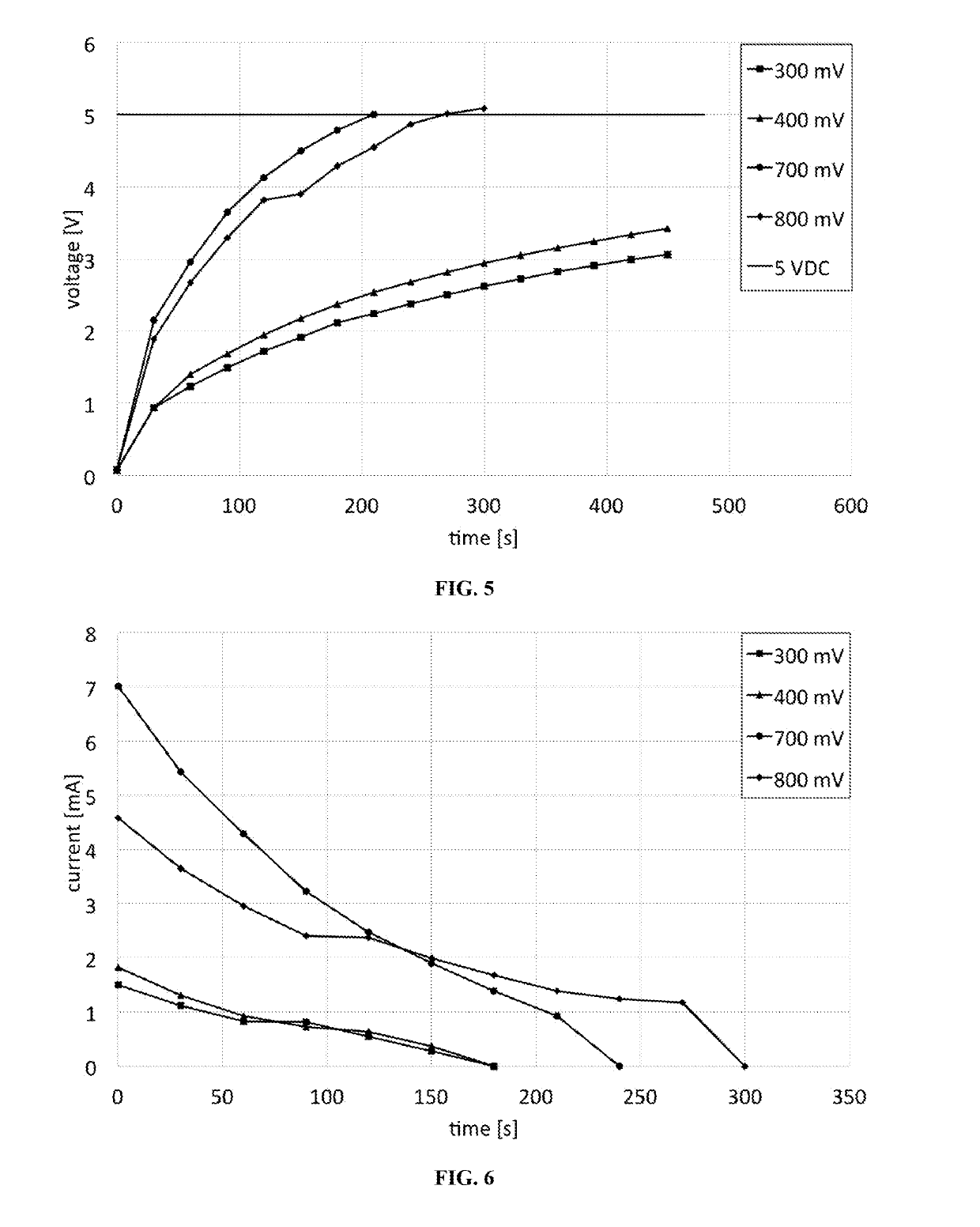
From these curves, it can be observed that increasing the input voltage to the system is not always the best strategy to recharge the capacitor faster.
For lower voltage values, the charging process can be very slow and take more than 10 minutes to reach the 5 VDC threshold.
In the experiments, cases were examined where the input signal to the rectifying circuit was too small and a useful amount of power could not be conveyed to recharge the capacitor.
One of the most challenging aspects faced by both traditional systems and futuristic designs is how to power or recharge the device under constraints on miniaturization while complying with low power levels allowed by the Food and Drug Administration (FDA).
However, the rate of sudden death in patients with cardiac implanted electronic devices (CIEDs) is still high and the physical and mental discomfort of wearing a pacemaker needs to be properly addressed [8].
In addition, to date, several clinical demands, e.g., leadless and endocardial pacing, subcutaneous ICD, and sensing and monitoring of heart failure, among others, have not received a satisfactory solution yet [27].
Miniaturization, long lifetime, and wireless networking capabilities are major requirements for a neurostimulator, but they are not completely met by existing and traditional devices.
Unfortunately, investments in early stages of innovation have seen a decline during the last years; conversely, financial support by investors is remarkable during the later stages of the development of a device.
Unique engineering challenges rise from the highly regulated market of IMDs [30].
This is a vital aspect, since implants can be defective [15] and lead to death in several cases [47].
The embedded electronic circuitry and subsystems require power, which, with biocompatibility issues, remains one of the major problematics in the design of implantable technologies and hindrance to miniaturization [6].
Implementing wireless powering methodologies that could substitute traditional batteries, is challenging, because both good energy transfer efficiency and high power levels are needed, but achieving them while meeting the FDA recommendations is one of the major difficulties.
Furthermore, using miniaturized components impacts the system performance, since they determine the maximum sustained power, which in some cases is too low.
However, adding function to the system increases the overall energy requirements.
On the one hand, batteries can offer enough energy to power an IMD, such as a pacemaker, for years; on the other, they pose three fundamental concerns that limit their applicability to IMDs.
Batteries are often too large in size, the materials used in their fabrication can be toxic for human tissues in case of leakages and, finally, once discharged, they have to be substituted through a surgical operation that entails economical costs, discomfort, and even death risk for the patient.
The main difficulties in creating an implantable harvester are related to the technology to fabricate the transducer and to the nature of the source.
For example, microelectromechanical systems (MEMS) and piezoelectric transducers scavenge kinetic energy mainly from human body motion (which is a discontinuous source, and therefore unreliable in many cases) and autonomous organ activities, such as breathing and heartbeat, that instead do not provide the necessary required power.
Electrostatic and electromagnetic (EM) converters are mechanically complex systems, which makes the miniaturization a challenging process.
After all, in the majority of both energy harvesting based approaches and TET solutions, the energy cannot be used the moment it is received or harvested.
Therefore, if an electronic circuitry implements the sensing, communication and data processing properly, but is too large or does not respect the power exposure limits, it cannot be implanted.
Furthermore, particular miniaturized solutions have to be found for wearable or patch-like devices thought to be attached to the skin.
These safety limitations translate into design constraints and impact the dimensioning of the whole system.
In each of the two conversion process, part of the input power is lost due to non-idealities of the devices.
The disadvantages are the higher number of capacitors and the lower current at the output.
However, having larger DC voltages is desirable in low-power circuits, because they allow recharging an energy storage component even when the received AC voltage is of the order of few hundreds of milliwatts and would not provide enough power with a rectifier.
The output voltage is directly proportional to n, however there is a limit on the maximum number of stages that can be used, as the conversion efficiency of the circuit is function of n. Higher voltages can be produced in output by increasing n, but the conversion efficiency decreases due to power loss caused by parasitic effects of the capacitors [33].
Moreover, increasing the number of stages also implies that more components need to be accommodated on the implant, occupying precious area on the board.
ASICs are designed and permanently configured only for one specific application; hence, they do not provide the flexibility and reconfigurability required in many cases.
Furthermore, design and fabrication of such systems are highly expensive and time consuming.
However, FPGAs performance can be from 5 to 25 times worse than ASIC implementations, and operations more complex to define with respect to microprocessor [19].
In reality, some parasite resistances, non-ideal behavior of the components, and the ESRs of the supercapacitors add up to a small resistive load.
These values are obtained bearing in mind that the supercapacitors cannot be completely depleted, since when the voltage drops to 2.5 V it is not sufficient to activate the leads.
Systems that use separate technologies for wireless power transfer and data communication introduce more complexity in the system and require more precious space on the implant, especially to accommodate capacitive coils or RF antennas in addition to the acoustic transducer that can play the same role.
The advantage of this principle is that the implant does not need energy for communication purposes, but the range of applications is limited, and intra-body networking is not possible, unless other nodes provides the power.
Energy harvesting for the implantable biomedical devices: issues and challenges.

Method used


Image

  • Reconfigurable Implantable Medical System For Ultrasonic Power Control And Telemetry
  • Reconfigurable Implantable Medical System For Ultrasonic Power Control And Telemetry
  • Reconfigurable Implantable Medical System For Ultrasonic Power Control And Telemetry

Examples


Embodiment Construction

[0058]A description of example embodiments follows.

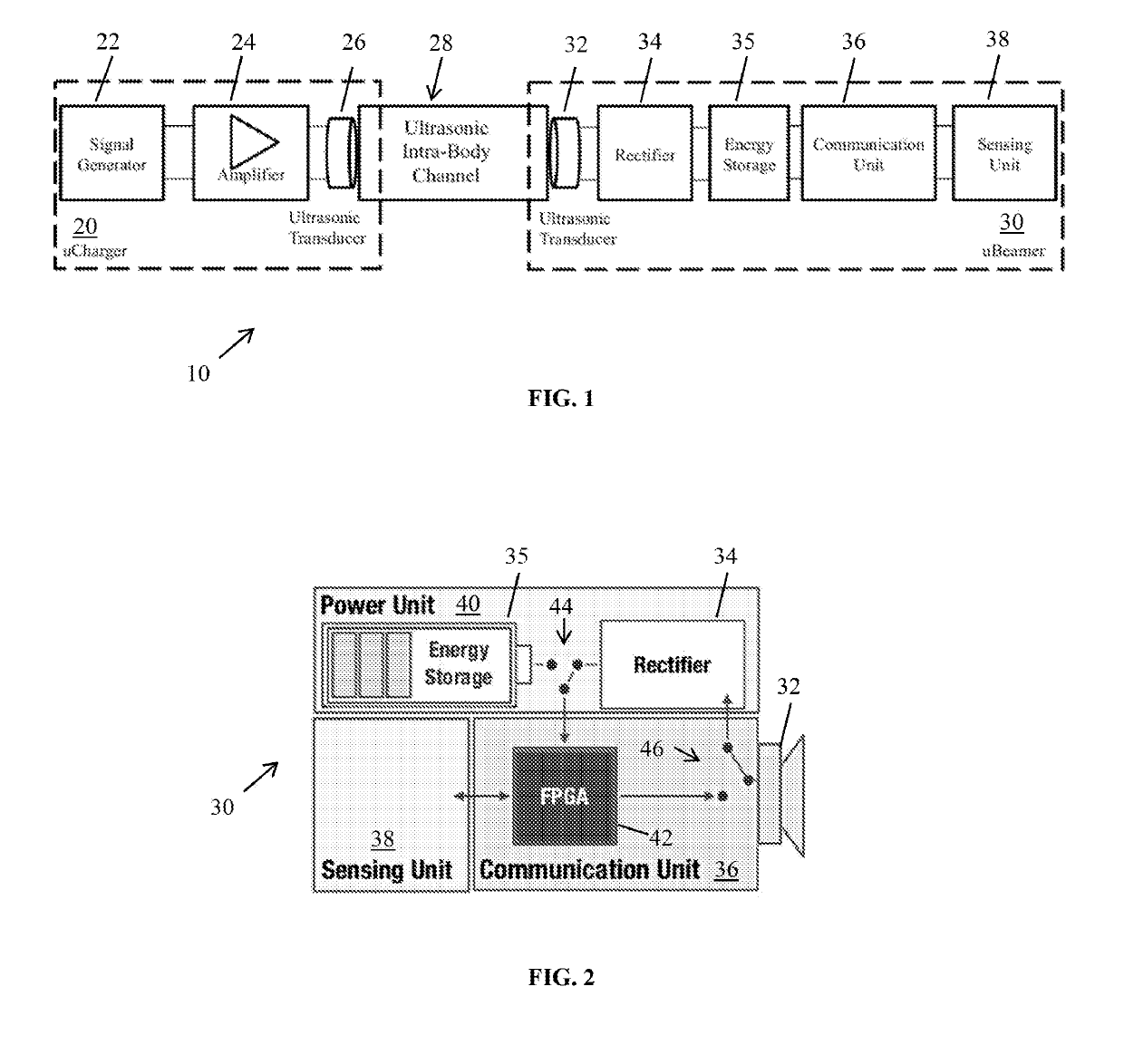
[0059]A reconfigurable implantable medical system and method are provided to enable wireless ultrasonic power control and telemetry via an intra-body communication link.

[0060]A prior ultrasonic network for wearable devices is described in International Application No. PCT / US2016 / 014814, by Melodia et al., filed Jan. 26, 2016, and published as WO 2016 / 123047 A1, the entire teachings of which are incorporated herein by reference.

[0061]A prior system and method for transmitting signals ultrasonically among a network of implantable and wearable devices are described in International Application No. PCT / US2016 / 014860, by Melodia et al., filed Jan. 26, 2016, and published as WO2016 / 123069 A1, the entire teachings of which are incorporated herein by reference.

[0062]With respect to the previous approaches, the current approach provides a system uniquely designed to manage energy, power transmission efficiency, and circuit interconnections t...


PUM


Abstract

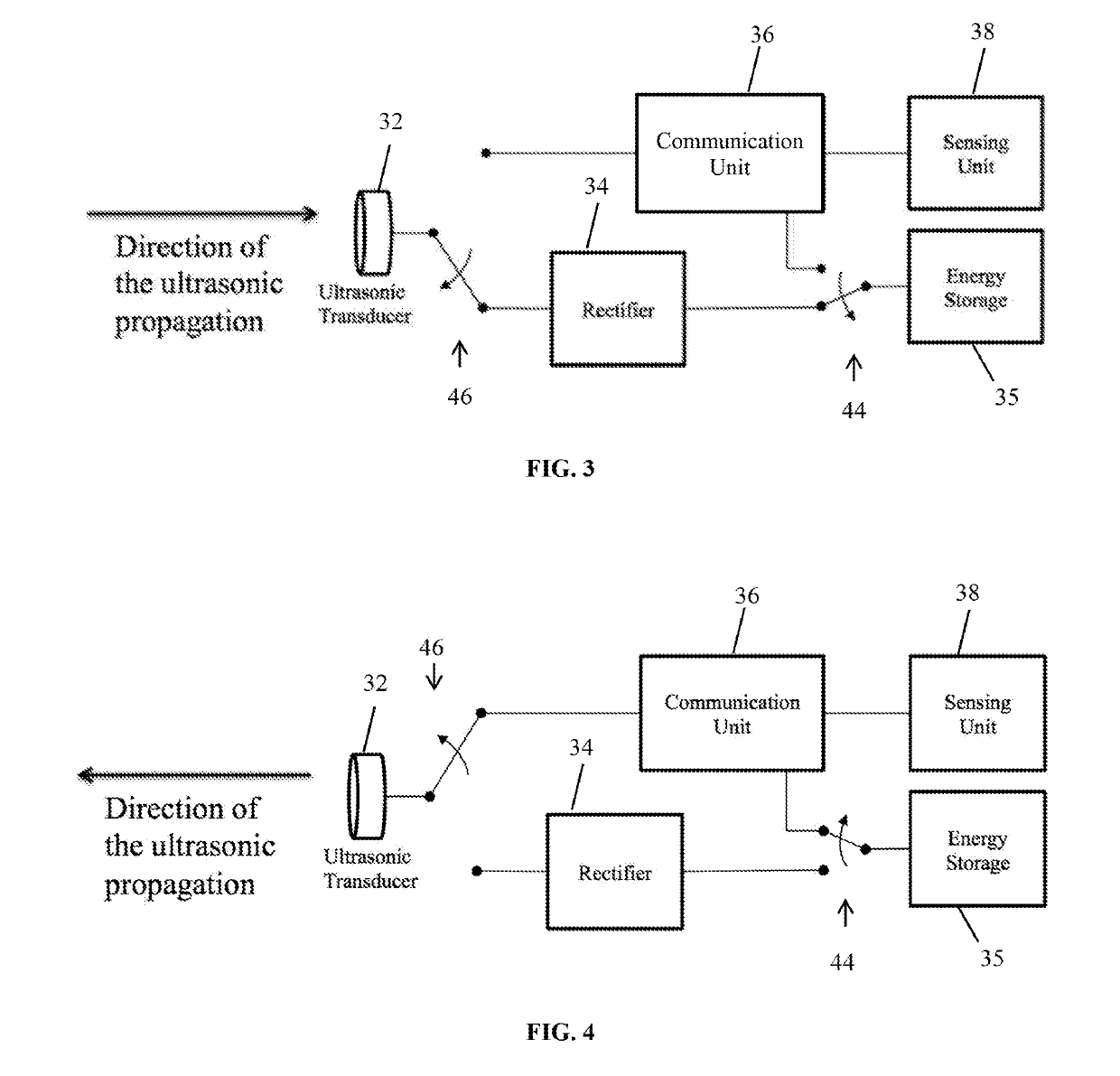
A reconfigurable implantable system for ultrasonic power control and telemetry includes a charging device that includes an ultrasonic transducer to transmit and receive ultrasonic signals transmitted through a biological body, and a signal generator to drive the ultrasonic transducer to transmit an ultrasonic charging signal through the biological body. The system further includes an implantable device configured to communicate wirelessly with the charging device through the biological body via an ultrasonic communication link between the implantable device and the charging device. An implantable ultrasonic transducer receives the ultrasonic charging signal from the charging device and transmits ultrasonic signals through the biological body. A power unit coupled to the ultrasonic transducer harvests energy from the received ultrasonic charging signal when the implantable device is in an energy harvesting mode. A communication unit is configured to switch the implantable device between the energy harvesting mode and an ultrasonic communication mode, and to read data from the sensing or actuation unit and transmit the data through the implantable ultrasonic transducer when the implantable device is in the ultrasonic communication mode.

Description

RELATED APPLICATION[0001]This application claims the benefit of U.S. Provisional Application No. 62 / 415,383, filed on Oct. 31, 2016. The entire teachings of the above application are incorporated herein by reference.BACKGROUND[0002]A variety of medical implantable devices (IMDs) have been developed in recent years that provide life-saving functionalities and enhance patients' quality of life. One challenging aspect faced by both traditional systems and future designs is how to power or recharge an implanted device under constraints on miniaturization while complying with low power levels allowed by the Food and Drug Administration (FDA). The next generation of implanted devices is expected to be endowed with wireless communication, sensing, processing, and actuation capabilities, which will increase the power requirements even more.GOVERNMENT SUPPORT[0003]This invention was made with government support under Grant No. CNS-1253309 from the National Science Foundation. The government ...

Claims


Application Information

Patent Timeline
IPC IPC(8): A61B5/00A61N1/378G08C23/02H02J7/02
CPCH02J7/025A61B5/7225H02J50/15A61B2560/0219G08C23/02H02J50/80A61B5/0015A61N1/3787A61B5/0028A61B5/0031A61B5/7278H02J7/00034H02J2310/23
Inventor MELODIA, TOMMASOGUIDA, RAFFAELESANTAGATI, GIUSEPPE ENRICO
Owner NORTHEASTERN UNIV
Learn More