Shear wave based elasticity imaging using three-dimensional segmentation for ocular disease diagnosis

a three-dimensional segmentation and elasticity imaging technology, applied in the field of ophthalmic imaging, can solve the problems of altering the elasticity of the surrounding layers and structures, insufficient early detection, etc., and achieve the effects of low signal-to-noise ratio, robust segmentation, and improved smoothness

Active Publication Date: 2019-11-07
RGT UNIV OF CALIFORNIA
View PDF0 Cites 3 Cited by
  • Summary
  • Abstract
  • Description
  • Claims
  • Application Information

AI Technical Summary

Benefits of technology

The present invention features an integrated system for in vivo imaging of ocular tissues using a confocal laser scanning ophthalmoscopy (cLSO), an ultrasound transducer for acoustic excitation, and an optical coherence tomography (OCT) detection. The unique system includes a co-aligned ARF excitation and OCT detection to measure the mechanical properties of ocular tissues. The 3-D segmentation algorithm and shear wave analysis / quantification algorithm is used to spatially map the elasticity of different posterior ocular layers, allowing for layer-specific shear wave elastic analysis and isolated tissue data from background signals. The system is robust against low signal to noise ratios and noises, and the combination of the dynamic programming and random walker algorithms ensures consistent and accurate segmentation of images with shear wave-induced displacement.

Problems solved by technology

Since traditional diagnosis methods for retinal and other ocular diseases rely on the identification of structural and vascular abnormalities, they may be insufficient for early detection when the anatomical abnormalities are not yet evident.
Additionally, any stiffness changes within the eye may alter the elasticity of the surrounding layers and structures due to the close-knit structure of the posterior eye.

Method used


Image

  • Shear wave based elasticity imaging using three-dimensional segmentation for ocular disease diagnosis
  • Shear wave based elasticity imaging using three-dimensional segmentation for ocular disease diagnosis
  • Shear wave based elasticity imaging using three-dimensional segmentation for ocular disease diagnosis

Examples


example

[0061]The following is a non-limiting example of the present invention. It is to be understood that said example is not intended to limit the present invention in any way. Equivalents or substitutes are within the scope of the present invention.

[0062]System Setup

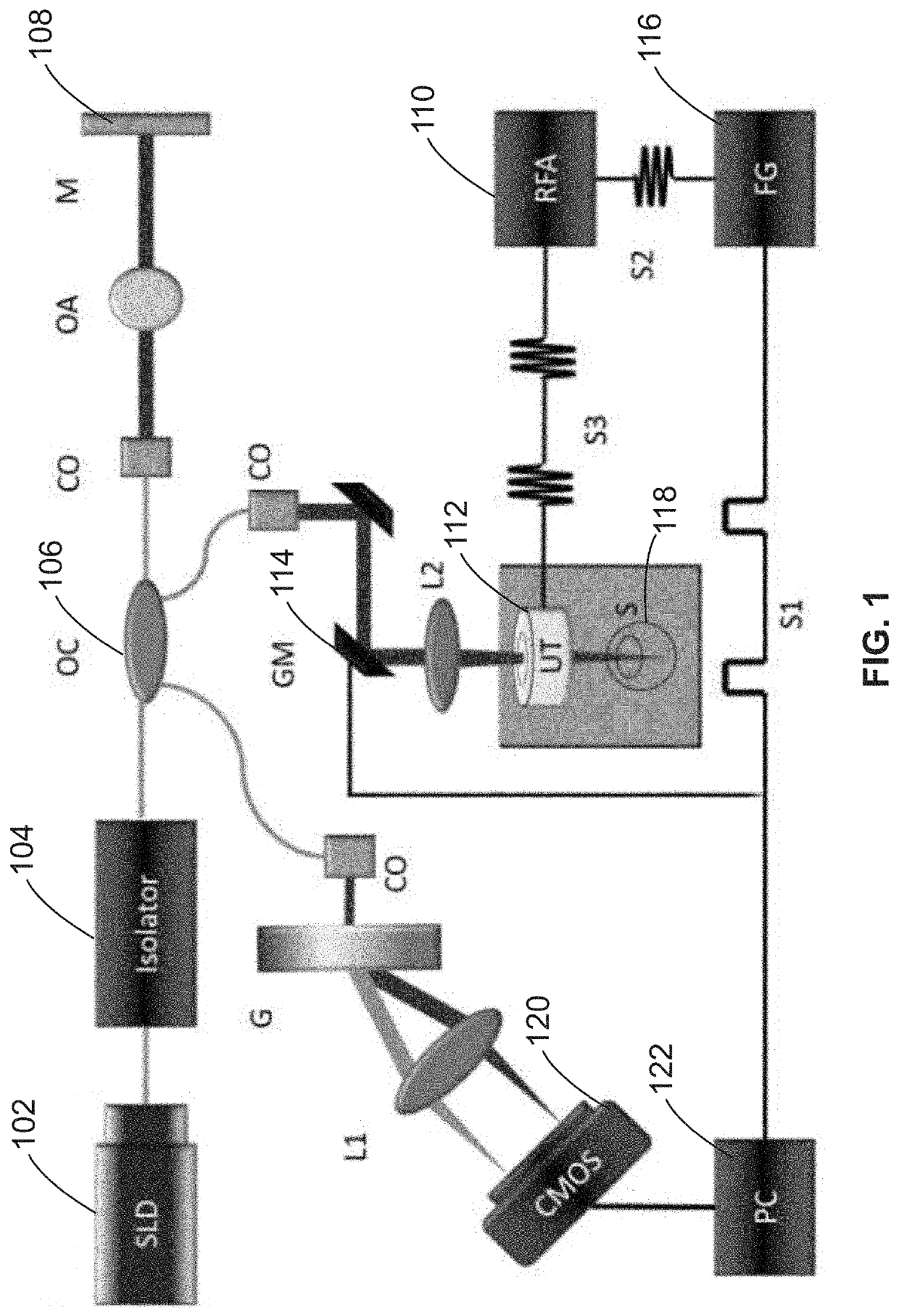
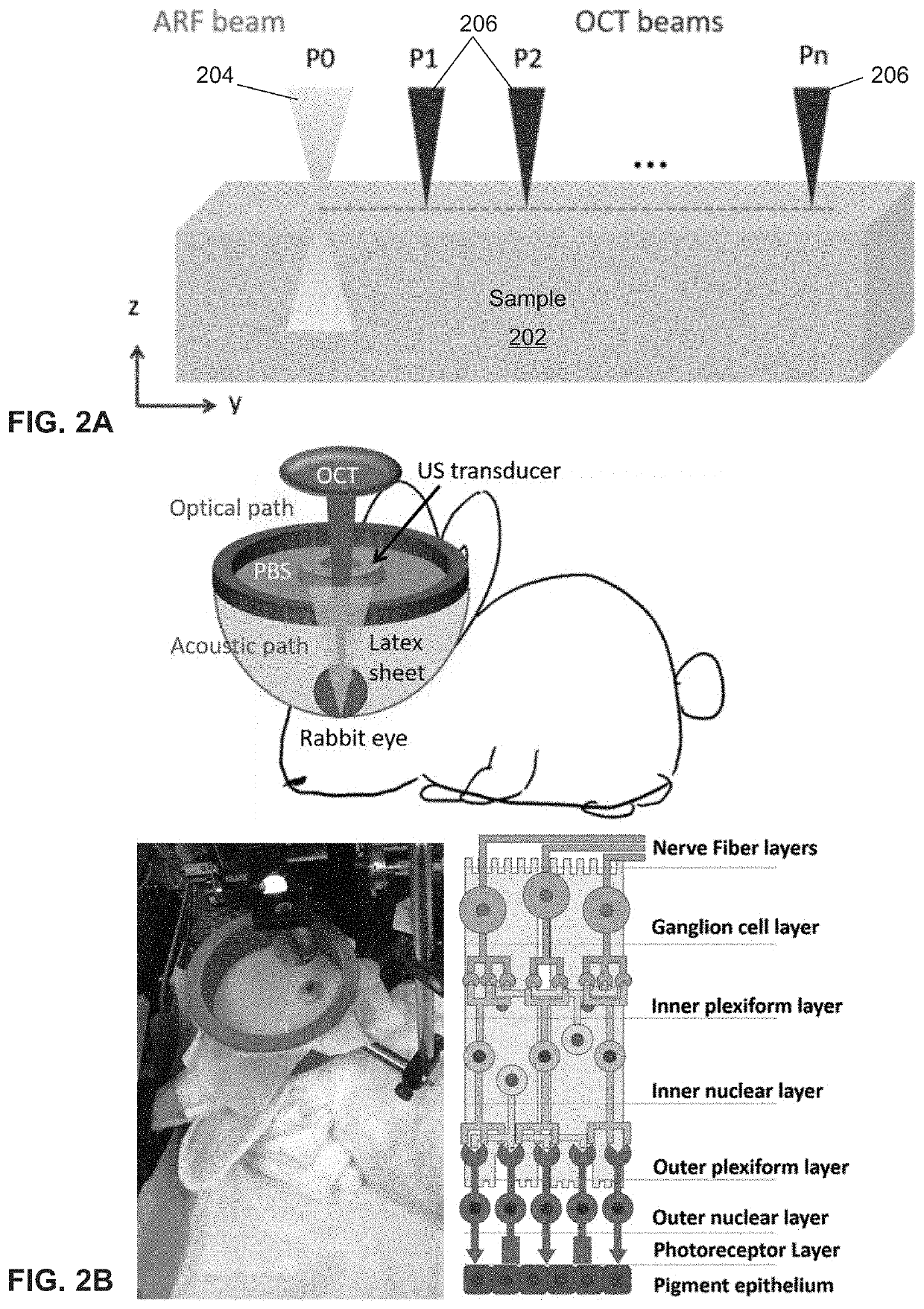
[0063]In some embodiments, a customized 50 kHz spectral domain optical coherence tomography (SD-OCT) system with a central wavelength of 890 nm and bandwidth of 144 nm is used for the detection of tissue structure and response to stimulation. The imaging depth range is 2.9 mm while the penetration depth in tissue is approximately 1.5 mm. In some other embodiments, a 4.5 MHz ring ultrasound transducer was used for pulsed tissue excitation. The excitation duration was limited to 1-2 ms while the optical detection speed was 50 kHz. The optical setup and the ex-vivo sample setup are shown in FIG. 2A, where a phosphate buffered saline (PBS) is used as the medium for ultrasound propagation as well as preservation of ocular tissue....


PUM


Abstract

Retinal diseases, such as age-related macular degeneration (AMD), are the leading cause of blindness in the elderly population. Since no known cures are currently present, it is crucial to diagnose the condition in its early stages so that disease progression is monitored. Systems and methods for detecting and mapping the mechanical elasticity of retinal layers in the posterior eye are disclosed herein. A system including confocal shear wave acoustic radiation force optical coherence elastography (SW-ARF-OCE) is provided, wherein an ultrasound transducer and an optical scan head are co-aligned to facilitate in-vivo study of the retina. In addition, an automatic segmentation algorithm is used to isolate tissue layers and analyze the shear wave propagation within the retinal tissue to estimate mechanical stress on the retina and detect early stages of retinal diseases based on the estimated mechanical stress.

Description

CROSS-REFERENCES TO RELATED APPLICATIONS[0001]This application is a non-provisional and claims benefit of U.S. Patent Application No. 62 / 666,980, filed May 4, 2018, the specification(s) of which is / are incorporated herein in their entirety by reference.GOVERNMENT SUPPORT[0002]This invention was made with government support under Grant Nos. EY026091, EY027666, EY028662 awarded by the National Institutes of Health. The government has certain rights in the invention.FIELD OF THE INVENTION[0003]The present invention relates to ophthalmic imaging, more particularly to elasticity imaging using optical coherence tomography (OCT) for ocular disease diagnosis.BACKGROUND OF THE INVENTION[0004]Age-related macular degeneration (AMD) is a progressive disease of the retina and is the leading cause of severe vision loss in the western population over 50 years of age. AMD most often induces drusen formation in the dry form, and neovascularization in wet AMD. Drusen often acts as an early sign of AM...

Claims


Application Information

Patent Timeline
IPC IPC(8): A61B3/12A61B3/10A61B8/10A61B8/08A61B3/14A61B8/00G06T7/12A61B5/00G06K9/62
CPCA61B3/14A61B8/10A61B3/102A61B8/4488A61B3/1225G06T7/12A61B8/485A61B8/5261G06T2207/20221A61B5/7264G06K9/6224G06T2207/20116A61B8/4494A61B8/488G06T2207/10101G06T2207/20081G06T2207/30041G06T2207/10132A61B8/4416A61B5/0051A61B5/442G06T7/0012G06V40/193G06V2201/03G06F18/2323
Inventor CHEN, ZHONGPINGHE, YOUMINQU, YUEQIAO
Owner RGT UNIV OF CALIFORNIA
Why Eureka
Try Eureka