
Flexible electromagnetic wave shielding material, electromagnetic wave shielding type circuit module comprising same and electronic device furnished with same

a technology of electromagnetic shielding and electromagnetic wave shielding, which is applied in the direction of shielding materials, printed circuit non-printed electric components association, filament/thread forming, etc., can solve the problems of malfunction of electronic devices, user who is using electronic devices may be harmfully affected, and cannot be easily shielded, so as to prevent deterioration of electromagnetic wave shielding performance, excellent flexibility, and creasing/recovery

Active Publication Date: 2020-03-26
AMOGREENTECH CO LTD
View PDF0 Cites 6 Cited by
  • Summary
  • Abstract
  • Description
  • Claims
  • Application Information

AI Technical Summary

Benefits of technology

The present invention provides electromagnetic wave shielding materials that are flexible, elastic, and can be easily changed in shape to fit different surfaces. These materials can prevent deterioration in electromagnetic wave shielding performance even when they are shaped differently. Additionally, these materials can be provided in close proximity to parts with high density, ensuring excellent electromagnetic wave shielding performance. This invention is useful for creating light, thin, short, and small or flexible electronic devices.

Problems solved by technology

The electric field is generated by voltage and is easily shielded due to long distances or obstacles such as a tree while the magnetic field is generated by current and is inversely proportional to a distance but is not easily shielded.
A recent electronic device is sensitive to electromagnetic interference (EMI) generated by an internal or external interference source, and there is a possibility of a malfunction of the electronic device being caused by electromagnetic waves.
Also, a user who is using an electronic device may be harmfully affected by electromagnetic waves generated by the electronic device.
In this case, it is difficult for the electromagnetic wave shielding material to exhibit flexibility and elasticity and it is not easy to change the electromagnetic wave shielding material to various shapes or to recover the electromagnetic wave shielding material.
Thus, the electromagnetic wave shielding material is difficult to employ in various application fields.
In particular, it may be difficult for the electromagnetic wave shielding material such as a metal plate or a metal thin film to fully exhibit electromagnetic wave shielding performance because the electromagnetic wave shielding material is difficult to bring into contact with a component requiring protection from an electromagnetic wave generating component or an electromagnetic wave source without a gap therebetween and also a crack may be generated due to bending at a stepped portion or an uneven portion.
However, the electromagnetic wave shielding material has limitation on electromagnetic wave shielding performance in accordance with the limitation of an available area of the supporting member to be coated.
Also, a film having a certain thickness or greater is insufficiently flexible, and thus may be difficult to bring into complete contact with components having a stepped portion or an uneven portion or to freely change in shape once manufactured in a specific shape.
Even when the shape change is possible, a crack, a delamination, or the like may frequently be generated in a covered conductive coating layer during the shape change.

Method used


Image

  • Flexible electromagnetic wave shielding material, electromagnetic wave shielding type circuit module comprising same and electronic device furnished with same
  • Flexible electromagnetic wave shielding material, electromagnetic wave shielding type circuit module comprising same and electronic device furnished with same
  • Flexible electromagnetic wave shielding material, electromagnetic wave shielding type circuit module comprising same and electronic device furnished with same

Examples


embodiment 1

[0218]A spinning solution was manufactured by dissolving 12 g of polyvinylidene fluoride in 88 g of dimethylacetamide and acetone, which were mixed at a weight ratio of 70:30, using a magnetic bar at a temperature of 80° C. for 6 hours. Spherical silver particles having an average particle diameter of 1.3μm were mixed with the spinning solution as conductive fillers such that the polyvinylidene fluoride and the sliver particles had a volume ratio of 1:0.2 and the sliver particles occupied 16.7% of the total volume of the final fiber part, and then were dispersed using an ultrasonic disperser for 12 hours. The spinning solution was poured into a solution tank of an electrospinning apparatus, stirred through an impeller, and then discharged at a rate of 20 μL / min / hole. In this case, a fiber web formed of an Ag / PVDF composite fiber in which a second part with no silver particles had an average diameter of 300 nm was manufactured by maintaining the temperature and humidity of the spinni...

embodiments 2 to 11

[0220]A conductive fiber web as shown in Table 1 was manufactured in the same way as in Embodiment 1, except that the amount and particle diameter of the conductive fillers were changed as shown in Table 1 or Table 2 below.

experimental example 1

[0222]The following physical properties of the conductive fiber webs according to Embodiments 1 to 11 and Comparative Example 1 were measured and shown in Table 1 and Table 2 below.

[0223]1. Initial Electromagnetic Wave Shielding Performance

[0224]The surface resistance of the conductive fiber web was measured through a resistance meter (HIOKI 3540 mΩ HITESTER, HIOKI). The measured resistance value according to the embodiment was expressed by a relative percentage with respect to the measured resistance value of Comparative Example 1 being set to 100.

[0225]2. Electromagnetic Wave Shielding Performance Variation

[0226]A specimen was elongated by a factor of 1.2 in the transverse direction and then by a factor of 1.2 in the longitudinal direction by means of a jig. This process was repeated three times.

[0227]Subsequently, a resistance value B for each specimen after elongation was found using the method of measuring the initial electromagnetic wave shielding performance, and a variation ...


PUM

PropertyMeasurementUnit
diameteraaaaaaaaaa
thicknessaaaaaaaaaa
thicknessaaaaaaaaaa

Abstract

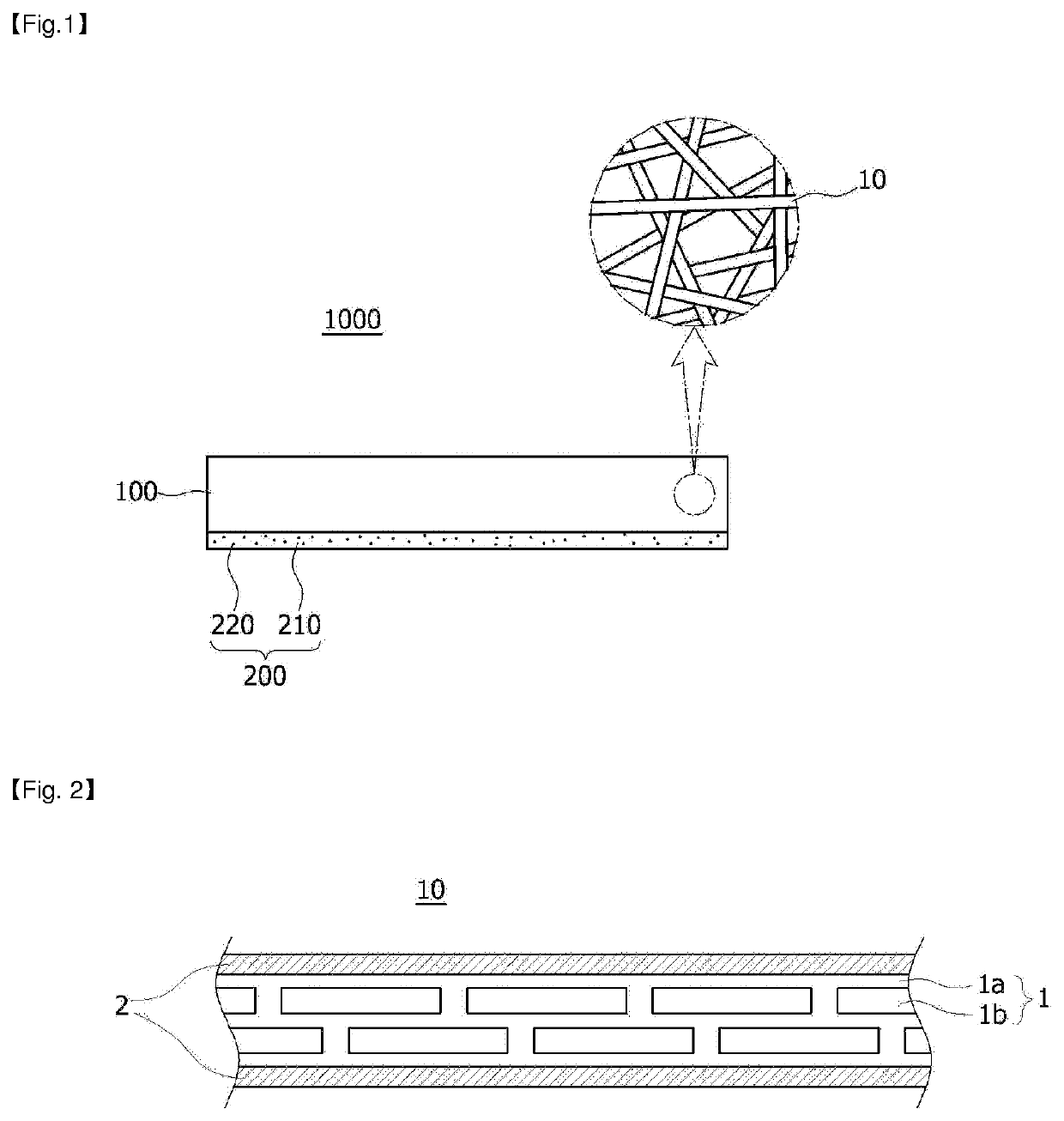
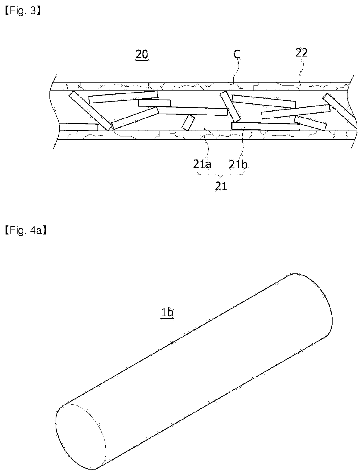
Provided is a flexible electromagnetic wave shielding material. An electromagnetic wave shielding material according to an embodiment of the present invention is implemented to include a conductive fiber web including a conductive composite fiber including a metal shell part covering an outside of a fiber part such that the conductive composite fiber forms multiple pores; and a first conductive component provided in at least some of the pores. The electromagnetic wave shielding material is so excellent in flexibility, elasticity, and creasing / recovery that the electromagnetic wave shielding material may be freely changed in shape, and can be brought in complete contact with a surface where the electromagnetic wave shielding material is intended to be disposed even if the surface has a curved shape such as an uneven portion or a stepped portion, thus exhibiting excellent electromagnetic wave shielding performance. Also, it is possible to prevent deterioration of the electromagnetic wave shielding performance even with various shape changes. Furthermore, even if parts are provided in a narrow area at a high density, the electromagnetic wave shielding material can be brought into complete contact with the mounted parts by overcoming a tight space between the parts and a stepped portion. Thus, the present invention can be easily employed for a light, thin, short, and small or flexible electronic device.

Description

CROSS REFERENCE TO RELATED APPLICATION[0001]This application is a 35 U.S.C. 371 National Phase Entry Application from PCT / KR2017 / 014552, filed Dec. 12, 2017, which claims the benefit of Korean Patent Application Nos. 10-2016-1068702 filed Dec. 12, 2016, 10-2016-168705 filed Dec. 12, 2016, 10-2016-0169487 filed Dec. 13, 2016, 10-2016-0169488 filed Dec. 13, 2016 and 10-2017-0170428 filed Dec. 12, 2017, the disclosures of which are incorporated herein in their entirety by reference.TECHNICAL FIELD[0002]The present invention relates to an electromagnetic wave shielding material, and more particularly, to a flexible electromagnetic wave shielding material having excellent flexibility, elasticity, and creasing / recovery, an electromagnetic wave shielding-type circuit module including the same, and an electronic device having the same.BACKGROUND ART[0003]Electromagnetic radiation is a phenomenon in which energy moves in a sinusoidal waveform while an electric field and a magnetic field coop...

Claims


Application Information

Patent Timeline
Patent Type & Authority Applications(United States)
IPC IPC(8): H05K9/00H05K1/18D01F8/00
CPCH05K9/0022D01F8/00H05K9/009D10B2401/16H05K1/181D01D5/0038D01F1/09D01F6/12D01F6/48D01F6/94D06M11/83D06M23/08D06M2101/22
Inventor SEO, IN YONGJEONG, UI YOUNGLEE, JUN WOO
Owner AMOGREENTECH CO LTD
Learn More