High throughput vacuum deposition sources and system thereof

a vacuum deposition source and high throughput technology, applied in chemical vapor deposition coatings, electric discharge tubes, coatings, etc., can solve the problems of low plasma density and low densities of reactive species, low ionization efficiency, and high process pressure to maintain stable plasma, etc., to achieve high throughput, reduce gas phase reactions and powder formation, and increase gas utilization

Inactive Publication Date: 2020-04-09
ASCENTOOL
View PDF2 Cites 2 Cited by
  • Summary
  • Abstract
  • Description
  • Claims
  • Application Information

AI Technical Summary

Benefits of technology

[0006]The present application discloses a high throughput deposition source and system for PECVD. Comparing to conventional systems, the disclosed source and system have higher gas utilization, reduced gas phase reactions and powder formations, reduced deposition on deposition sources, increased lifetime of deposition sources, minimized the process condition variation throughout source life time, reduced waste treatment, increased system productivity, and can eliminate physical contacts between workpieces and deposition system during processing.

Problems solved by technology

One challenge for parallel-plate PECVD is the relative low plasma density and low densities of reactive species, which require relatively high process pressures to maintain stable plasma.
The higher process pressure leads to low ionization efficiency and high rate of reactions in gas phase, resulting in low material utilization, powder formation and expensive waste gas treatment system.
Another challenge for PECVD is deposition on the plasma sources, which can lead to particulates formation, clogging of gas distribution holes, and change in plasma conditions.
The in-situ cleaning of the plasma sources not only takes time, but is also impractical for some applications such as roll-to-roll web processing where the workpieces are always present.
Any physical contact with the workpieces before the entire process is complete is detrimental to the workpieces.

Method used


Image

  • High throughput vacuum deposition sources and system thereof
  • High throughput vacuum deposition sources and system thereof
  • High throughput vacuum deposition sources and system thereof

Examples


Embodiment Construction

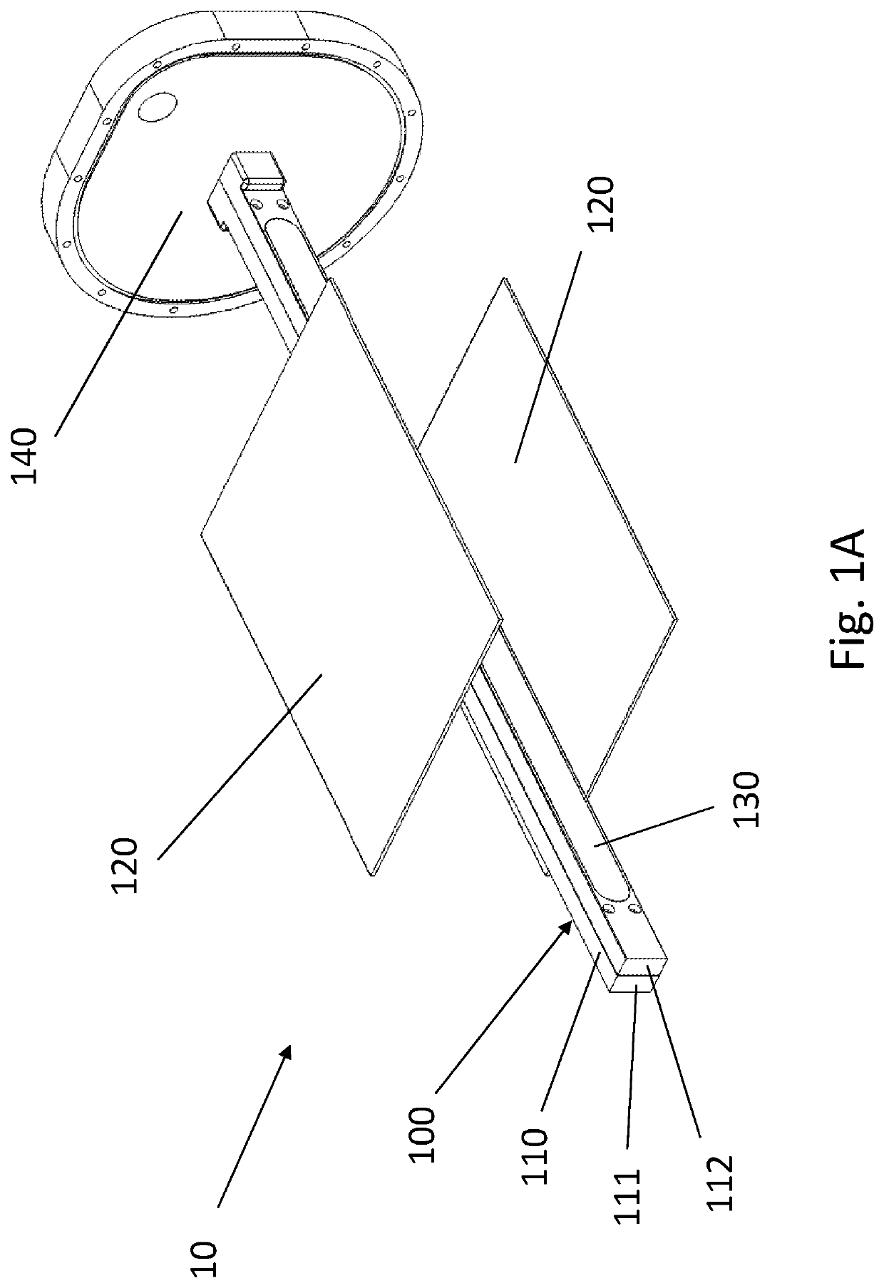
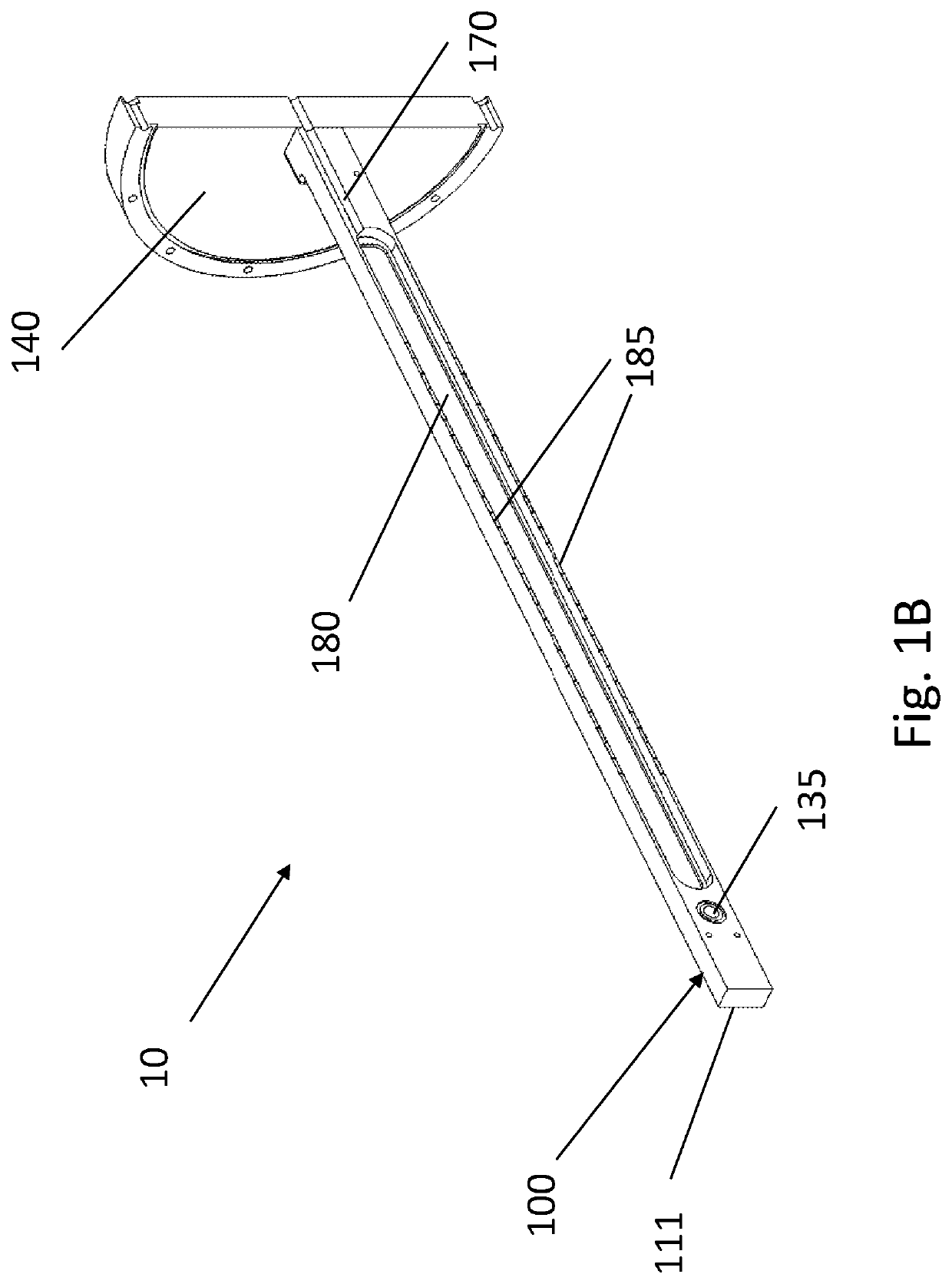
[0019]FIGS. 1A and 1B show a portion of a vacuum deposition system 10 comprising a deposition source such as a plasma source 100, and one or more workpieces 120, which are placed inside a vacuum chamber (not shown). The deposition source such as the plasma source 100 has an elongated shape, which includes an electrode 110 in elongated shape. The one or more workpieces 120 are positioned on one side or multiple sides of the electrode 110, all inside the vacuum chamber (not shown) in which the atmosphere gases are evacuated and back filled with desirable gases such as argon, Silane, nitrogen, et al.

[0020]In operation, a voltage such as radio frequency (RF) power is applied between workpieces and the electrode and a plasma is formed with aid of the back filled gases. Unlike conventional parallel-plate PECVD sources which includes a pair of counter electrodes (a cathode and an anode), the disclosed plasma source 100 only includes an electrode with one polarity (a cathode or an anode); t...


PUM

PropertyMeasurementUnit
electrically biasedaaaaaaaaaa
polarityaaaaaaaaaa
temperatureaaaaaaaaaa

Abstract

A high throughput deposition apparatus includes a vacuum chamber comprising a first processing chamber, a plurality of elongated deposition sources in parallel in the first processing chamber, wherein each of the elongated deposition sources can include a gas distribution channel that provides a deposition material in a gas form, and an electrode configured to generate a plasma in the deposition material, and a web transport mechanism configured to move a plurality of workpiece webs passing by the elongated deposition sources in the first processing chamber. The plurality of workpiece webs are parallel to each other and are configured to receive the deposition material in the first process chamber.

Description

BACKGROUND OF THE INVENTION[0001]The present application relates to material deposition technologies, and more specifically to high throughput deposition apparatus.[0002]Vacuum depositions such as sputtering, chemical vapor deposition (CVD), or plasma enhanced chemical vapor deposition (PECVD) are used in many industries to deposit materials on workpieces such as web, glass, semiconductor wafers, hard disks, et al.[0003]For material depositions on rectangular shaped workpieces and webs, PECVD is often applied between parallel plates to achieve good uniformity. One challenge for parallel-plate PECVD is the relative low plasma density and low densities of reactive species, which require relatively high process pressures to maintain stable plasma. The higher process pressure leads to low ionization efficiency and high rate of reactions in gas phase, resulting in low material utilization, powder formation and expensive waste gas treatment system. Another challenge for PECVD is depositio...

Claims


Application Information

Patent Timeline
Patent Type & Authority Applications(United States)
IPC IPC(8): C23C16/50C23C16/54
CPCC23C16/50C23C16/545H01J37/3244C23C16/45578H01J37/3277H01J37/32541H01J37/32091H01J37/32568H01J37/3266H01J37/32669H01J37/32706
Inventor GUO, GEORGE XINSHENG
Owner ASCENTOOL
Why Eureka
Try Eureka