
Gas Analyzer For Measuring Nitrogen Oxides And Least One Further Component Of An Exhaust Gas

a gas analyzer and nitrogen oxide technology, applied in the field of gas analyzers, can solve the problems of nitrogen oxide compounds that are undesirable for the measurement of nitrogen oxide in the exhaust gas, and achieve the effect of constant residence time and enhanced performan

Active Publication Date: 2020-06-25
SIEMENS AG
View PDF0 Cites 2 Cited by
  • Summary
  • Abstract
  • Description
  • Claims
  • Application Information

AI Technical Summary

Benefits of technology

The invention is about an oxidation device for gas analysis that uses high-energy radiation to generate ozone from atmospheric oxygen. This ozone is then used to convert nitrogen monoxide in the exhaust gas to nitrogen dioxide. The device contains an ozone generator with an ultraviolet light source and a reaction chamber where the exhaust gas passes through. The concentration of nitrogen monoxide in the exhaust gas is relatively low, so only a small amount of ozone is consumed during the conversion process. The device measures the ozone concentration in the partially treated exhaust gas as a measure of the oxygen concentration in the untreated exhaust gas. The relationship between these two gases can be easily calibrated to determine the oxygen concentration. This device has improved accuracy and sensitivity compared to previous designs, making it useful for gas analysis applications.

Problems solved by technology

The disadvantage of the generation of ozone from atmospheric oxygen as mentioned in the publication by Ryoichi Higashi et al via electric discharge (corona discharge), is the formation of nitrogen oxide compounds that are undesirable for the measurement of nitrogen oxide in the exhaust gas.

Method used


Image

  • Gas Analyzer For Measuring Nitrogen Oxides And Least One Further Component Of An Exhaust Gas
  • Gas Analyzer For Measuring Nitrogen Oxides And Least One Further Component Of An Exhaust Gas
  • Gas Analyzer For Measuring Nitrogen Oxides And Least One Further Component Of An Exhaust Gas

Examples


Embodiment Construction

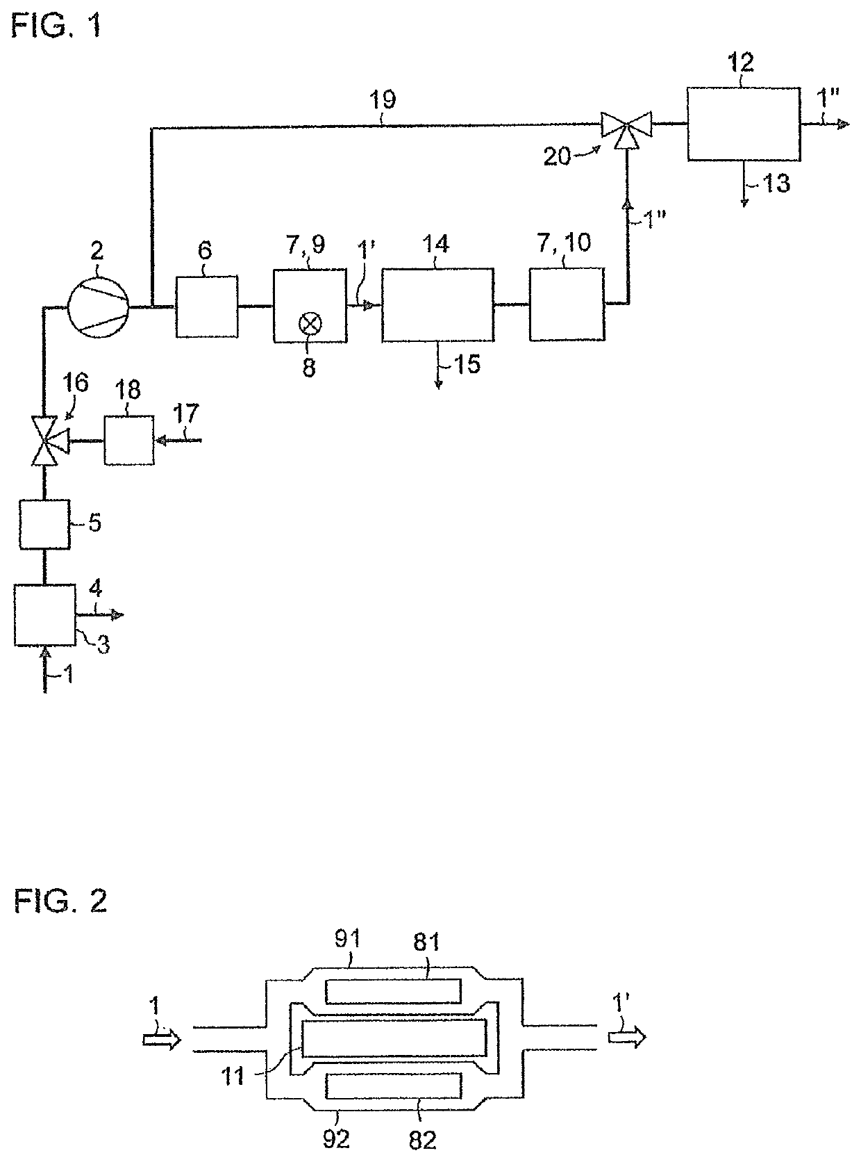
[0022]FIG. 1 shows a simplified schematic representation of a block diagram of a gas analyzer for measuring nitrogen oxides, sulfur dioxide and oxygen in an exhaust gas 1. The exhaust gas 1 is drawn in via a sample gas pump 2 from a sampling point through a gas cooler 3 with a condensate outlet 4 and a fine particle filter 5. The gas cooler 3 serves to prevent condensation of water in the gas analyzer. The throughflow of the exhaust gas 1 is set as constant with the aid of a throughflow regulator 6 in the form of a mass throughflow regulator or pressure regulator with a subsequent throttle.

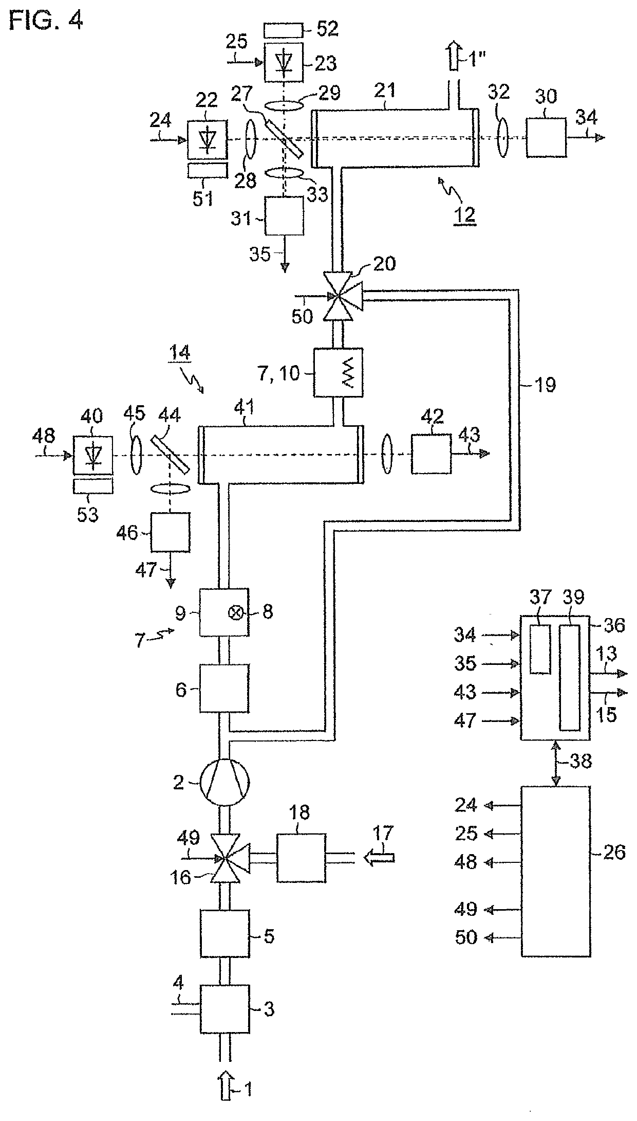
[0023]In order to facilitate the measurement of the nitrogen oxide concentration, the exhaust gas 1 is treated in a two-stage oxidation device 7, which comprises an ozone generator in the form of an ultraviolet light source 8 in a reaction chamber 9 through which the exhaust gas 1 flows in a first stage and a heating chamber 10 in a second stage. With its radiation of, for example, 185 nm, the ult...


PUM

PropertyMeasurementUnit
emission wavelengthaaaaaaaaaa
absorption wavelengthaaaaaaaaaa

Abstract

A gas analyzer includes an oxidation device and a subsequent photometer, wherein the oxidation device has a reaction chamber located in an exhaust gas path and a heating chamber downstream thereof, where an ultraviolet light source generates ozone from residual oxygen content of the exhaust gas within the reaction chamber to convert nitrogen monoxide into nitrogen dioxide in the exhaust gas, nitrogen oxides and excess ozone are broken down into nitrogen dioxide and oxygen in the heating chamber, the photometer outputs the measured nitrogen dioxide concentration as nitrogen oxide concentration of the untreated exhaust gas, and where an additional photometer is located in the exhaust gas path between the reaction chamber and the heating chamber which, via light absorption, measures the ozone concentration in the partially treated exhaust gas and outputs the same as oxygen concentration of the untreated exhaust gas.

Description

CROSS-REFERENCE TO RELATED APPLICATIONS[0001]This is a U.S. national stage of application No. PCT / EP2018 / 069201 filed Jul. 16, 2018. Priority is claimed on German Application No. 102017213980 filed Aug. 10, 2017, the content of which is incorporated herein by reference in its entirety.BACKGROUND OF THE INVENTION1. Field of the Invention[0002]The invention relates to a gas analyzer for measuring nitrogen oxides and at least one further component of an exhaust gas with an oxidation device comprising an ozone generator, a reaction chamber located in an exhaust gas path and a heating chamber located downstream thereof in the exhaust gas path and which is configured to treat the exhaust gas with generated ozone in the reaction chamber to convert nitrogen monoxide into nitrogen dioxide and to induce thermal decomposition of nitrogen oxides and excess ozone into nitrogen dioxide and oxygen in the heating chamber and with a photometer located downstream of the oxidation device in the exhaus...

Claims


Application Information

Patent Timeline
Patent Type & Authority Applications(United States)
IPC IPC(8): G01N21/33G01N33/00G01N21/85
CPCG01N33/0039G01N33/0037G01N21/85G01N2021/8578G01N33/0042G01N2201/0625G01N2201/121G01N21/33G01N33/0024Y02A50/20
Inventor HEFFELS, CAMIELSCHMIDT, BENJAMIN
Owner SIEMENS AG
Learn More