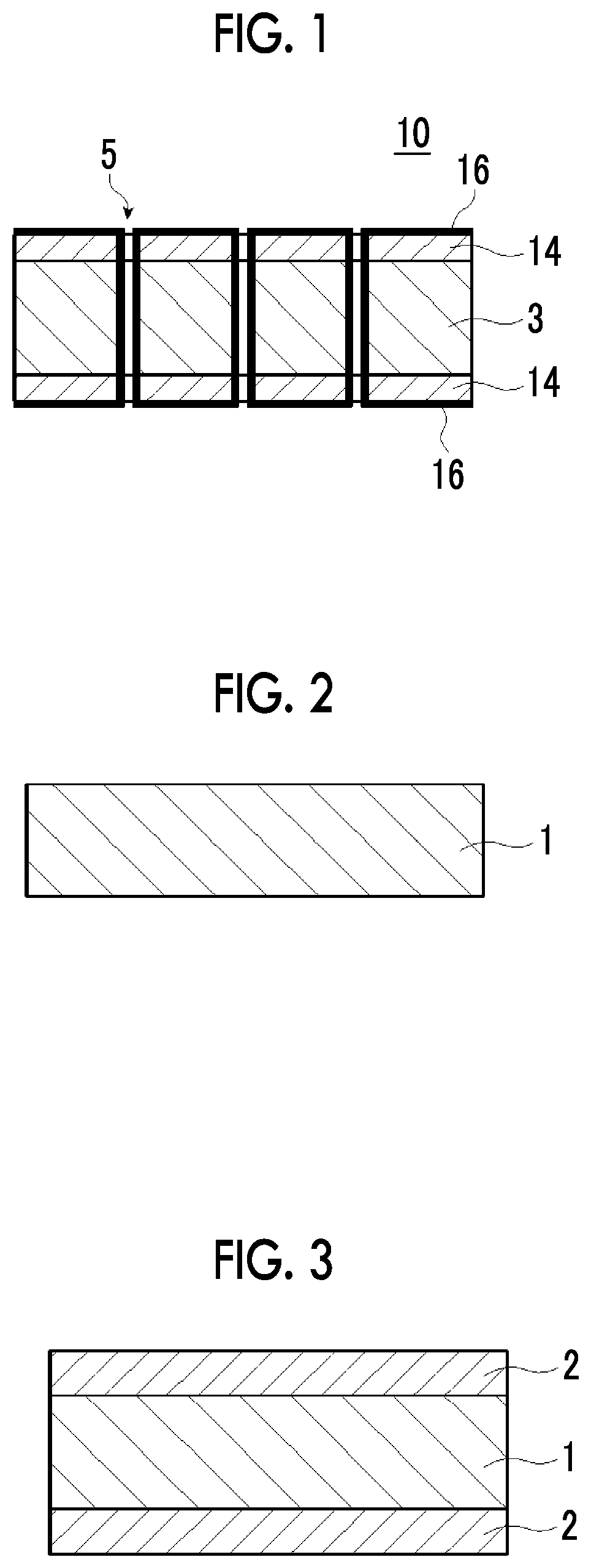
Aluminum foil and aluminum member for electrodes
a technology of aluminum foil and electrodes, applied in the direction of cell components, superimposed coating processes, electrochemical generators, etc., can solve the problem of insufficient use of aluminum, and achieve the effect of good adhesiveness and high conductivity
- Summary
- Abstract
- Description
- Claims
- Application Information
AI Technical Summary
Benefits of technology
Problems solved by technology
Method used
Image
Examples
example 1
[0197]
[0198](Formation of Through Hole)
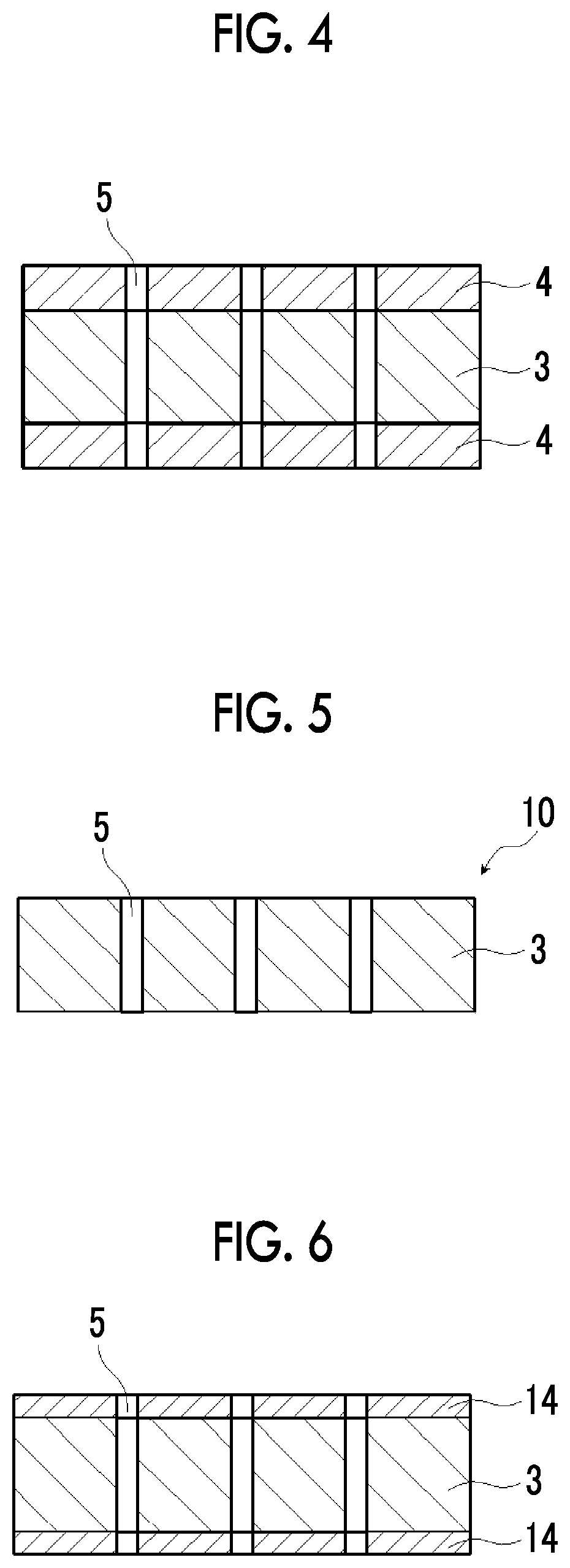
[0199]With reference to Example 1 of JP2011-208254A, the conditions were adjusted as follows, and through holes were formed in an aluminum substrate by an electrolytic method.
[0200]An ingot having an aluminum purity of 99.99% was prepared, and a homogenization treatment, hot rolling (temperature: 400° C.), cold rolling, intermediate annealing, and cold rolling again were carried out to obtain an aluminum substrate having a thickness of 30 μm. After cleaning the surface, annealing was performed at 500° C. for 10 hours in argon gas. By this annealing, the crystal orientation of aluminum can be aligned in the substantially same direction. Then, by carrying out a direct current etching was carried out using an aqueous solution containing 5% by mass of hydrochloric acid as an electrolytic solution, tunnel pits were formed and caused to penetrate the aluminum substrate to form through holes having an average opening diameter of 1 μm and a hole densit...
example 2
[0208]An aluminum foil was prepared in the same manner as in Example 1 except that the method of forming the through holes was changed as follows, the average opening diameter of the through holes was 11 μm, and the hole density was 110 holes / mm2.
[0209](a) Aluminum Hydroxide Film Forming Treatment (Film Forming Step)
[0210]An aluminum substrate having an average thickness of 20 μm (JIS H-4160, alloy number: 1N30-H, aluminum purity: 99.30%) was prepared.
[0211]An electrolytic treatment was carried out under a condition of a sum of quantities of electricity of 500 C / dm2 using an electrolytic solution (nitric acid concentration: 1%, sulfuric acid concentration: 0.2%, aluminum concentration: 0.5%) which was held at 50° C. and the above-described aluminum substrate as a cathode, thereby forming an aluminum hydroxide film on the aluminum substrate. Meanwhile, the electrolytic treatment was carried out using a direct current power supply. The current density was set to 50 A / dm2.
[0212]After t...
example 3
[0219]An aluminum foil was prepared in the same manner as in Example 2 except that the total amount of electricity in (a) film forming step above was changed to 1000 C / dm2 and the total amount of electricity in (b) through hole forming step above was changed to 1000 C / dm2, the average opening diameter of the through holes was set to 20 μm, and the hole density was set to 160 holes / mm2.
PUM
| Property | Measurement | Unit |
|---|---|---|
| thickness | aaaaa | aaaaa |
| thickness | aaaaa | aaaaa |
| opening diameter | aaaaa | aaaaa |
Abstract
Description
Claims
Application Information
 - R&D
- Intellectual Property
- Life Sciences
- Materials
- Tech Scout
- Unparalleled Data Quality
- Higher Quality Content
- 60% Fewer Hallucinations
Browse by: Latest US Patents, China's latest patents, Technical Efficacy Thesaurus, Application Domain, Technology Topic, Popular Technical Reports.
© 2025 PatSnap. All rights reserved.Legal|Privacy policy|Modern Slavery Act Transparency Statement|Sitemap|About US| Contact US: help@patsnap.com


