Fluid-assisted thermal management of evaporation sources

a technology of evaporation source and thermal management, which is applied in the field of thermal evaporation, can solve the problems of less effective coupling heat into evaporation source operation, process loss, etc., and achieve the effects of high thermal mass, simplified control of thermal evaporation process, and high efficiency

Inactive Publication Date: 2021-07-01
FIRST SOLAR INC (US)
View PDF4 Cites 0 Cited by
  • Summary
  • Abstract
  • Description
  • Claims
  • Application Information

AI Technical Summary

Benefits of technology

[0006]Conventional systems with high thermal mass have the added advantage that control of the thermal evaporation process is simplified as temperature fluctuations based on power fluctuations to the heaters are typically negligible. Highly effective thermal insulation further reduces sensitivity to incoming power fluctuations. Such thermal insulation also reduces heat losses to the surroundings, i.e., it increases thermal coupling efficiency of the electrical heater power to the material to be evaporated, leading to lower operating costs. In summary, high thermal mass and highly effective thermal insulation are important aspects of conventional industrial thermal evaporation processes.

Problems solved by technology

However, this process starts to lose effectiveness the lower the temperature of the body to be cooled and the smaller the temperature difference between the body cooling down and the system absorbing the thermal energy.
Thus, in a vacuum environment, cooling via radiation is typically most effective above approximately 300° C. Similarly, coupling heat into evaporation sources operating at low temperatures (e.g., <400° C.) via radiation is also less effective, in particular if the material is one with poor thermal conductivity (e.g., P, S, or Se).
Such concerns complicate both the reservoir and resistive heater design, as well as thermal evaporation rate control of these high-vapor-pressure elements.

Method used


Image

  • Fluid-assisted thermal management of evaporation sources
  • Fluid-assisted thermal management of evaporation sources
  • Fluid-assisted thermal management of evaporation sources

Examples


Embodiment Construction

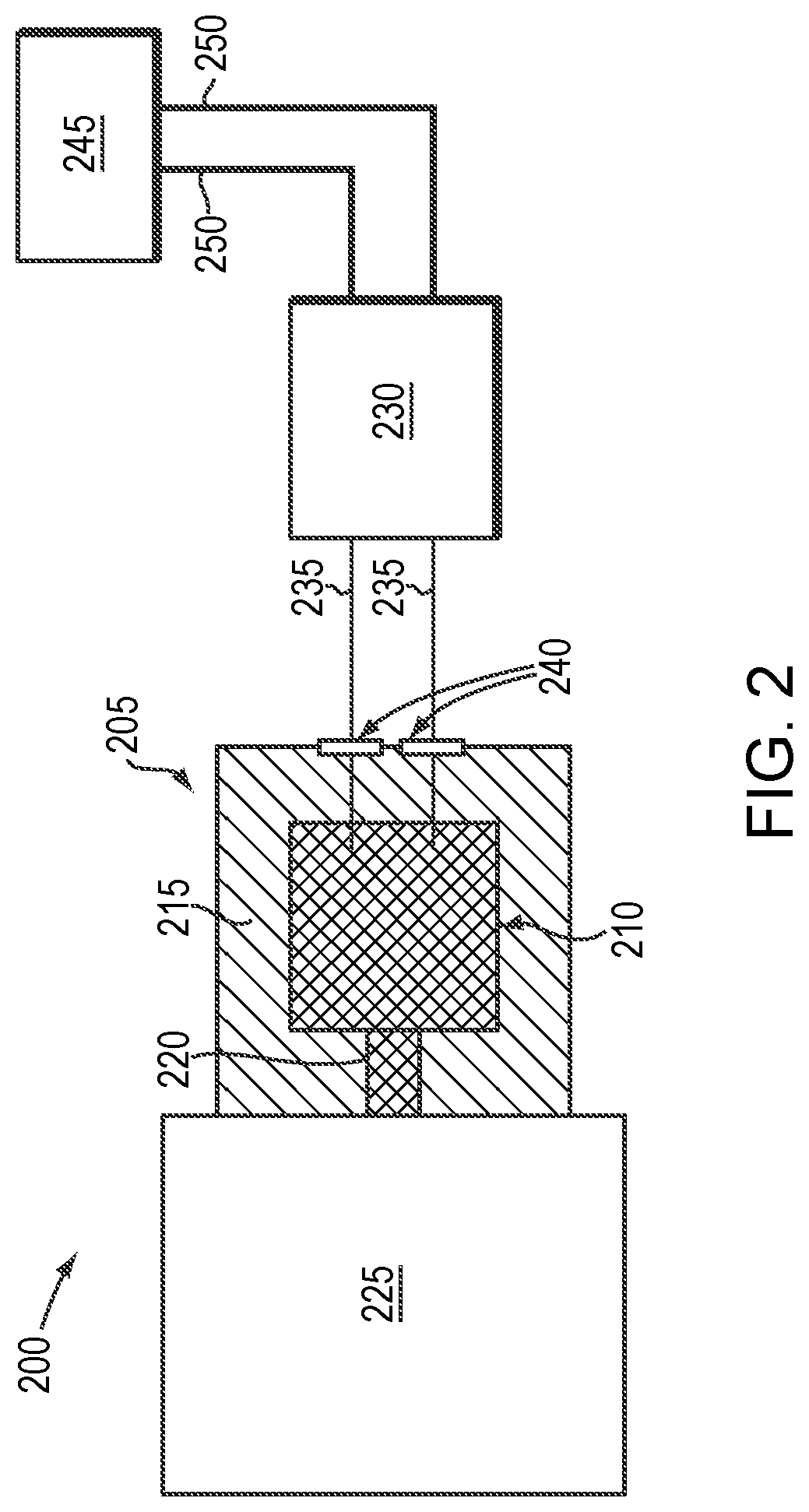
lass="d_n">[0039]FIG. 2 is a schematic diagram of an exemplary deposition system 200 in accordance with embodiments of the present invention. As shown, the system 200 features a thermal evaporation source 205 incorporating a reservoir 210 for feedstock material to be evaporated. The reservoir 210 is at least partially surrounded by a vacuum shell 215 that enables the establishment and maintenance of very low pressures (i.e., very high vacuums) in the deposition system 200. The source reservoir 210 has an evaporation port 220 through which the evaporant leaves the source 205 and enters a deposition chamber 225 for, e.g., deposition on one or more substrates. While only one evaporation source 205 is depicted in FIG. 2 for simplicity, embodiments of the present invention utilize two or more evaporation sources (e.g., for evaporation of different materials). Multiple evaporation sources may share a single fluid-based thermal management system, or each evaporation source may utilize its ...


PUM

PropertyMeasurementUnit
temperatureaaaaaaaaaa
temperaturesaaaaaaaaaa

Abstract

In various embodiments, evaporation sources for deposition systems are heated and/or cooled via a fluid-based thermal management system.

Description

CROSS-REFERENCE TO RELATED APPLICATIONS[0001]This application is a continuation of U.S. patent application Ser. No. 15 / 904,647, filed Feb. 26, 2018, which is a continuation of U.S. patent application Ser. No. 15 / 082,290, filed Mar. 28, 2016, which claims the benefit of and priority to U.S. Provisional Patent Application No. 62 / 140,083, filed Mar. 30, 2015, the entire disclosure of each of which is hereby incorporated herein by reference.TECHNICAL FIELD[0002]In various embodiments, the present invention relates to thermal evaporation, in particular to thermal management of evaporation sources.BACKGROUND OF THE INVENTION[0003]Thermal evaporation is a well-known approach to forming a number of materials such as III-V solid-state semiconductors via molecular beam epitaxial (MBE) growth. Another commercial application of this technique is the evaporation of aluminum (Al) onto polymer foils for the packaging industry or other metals onto polymer foils for capacitor manufacturing. In these...

Claims


Application Information

Patent Timeline
Patent Type & Authority Applications(United States)
IPC IPC(8): C23C14/26C23C14/24C23C14/54F28D15/00H01L31/046C23C16/448F25B39/00H01L31/032H01L31/18H01L51/00H01L51/56C23C16/02C23C16/28C23C16/52F25D17/02
CPCC23C14/26F25B39/02C23C14/243C23C14/542F28D15/00H01L31/046C23C16/4485F25B39/00H01L31/0322H01L31/0326H01L31/18H01L51/001H01L51/56C23C16/0209C23C16/28C23C16/448C23C16/52F25D17/02Y02E10/541C23C14/24H10K71/00H10K71/164H01L21/02568H01L21/02631
Inventor BECK, MARKUS EBERHARDBONNE, ULRICH ALEXANDERWENDT, ROBERT G.
Owner FIRST SOLAR INC (US)
Why Eureka
Try Eureka