Practical ion mobility spectrometer apparatus and methods for chemical and/or biological detection

a technology of ion mobility and spectrometer, which is applied in the direction of electron/ion optical arrangement, particle separator tube details, instruments, etc., can solve the problems of high power consumption, limited performance of ion mobility based spectrometer, and many limitations of chemical and/or biological analytical instruments currently used for sample analysis, etc., to achieve rapid temperature modulation, increase the temperature of the drift tube, and simple construction

Active Publication Date: 2021-07-22
WU CHING
View PDF0 Cites 0 Cited by
  • Summary
  • Abstract
  • Description
  • Claims
  • Application Information

AI Technical Summary

Benefits of technology

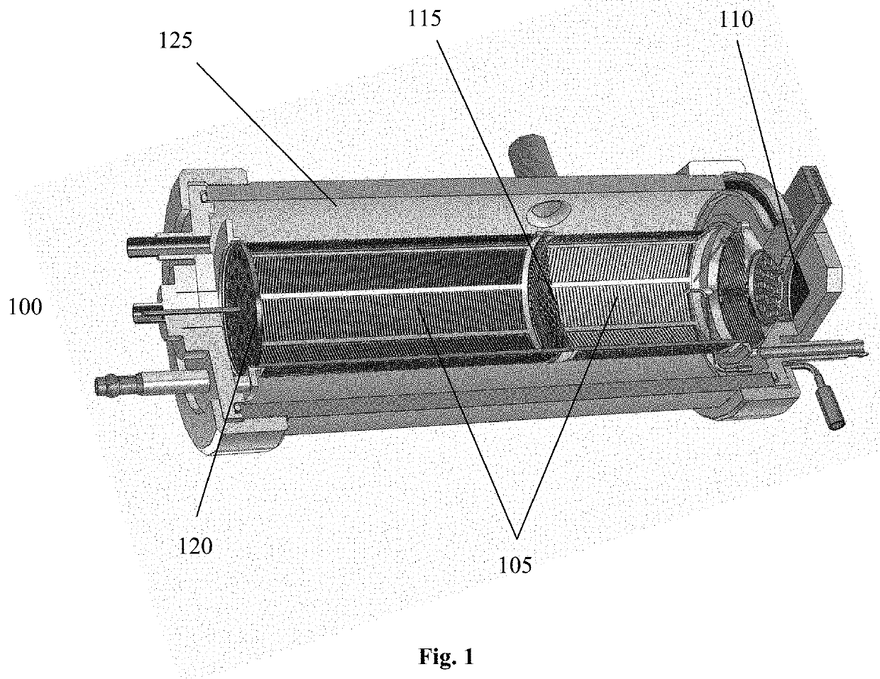
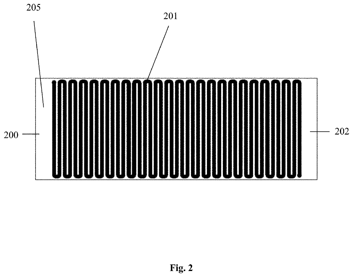
[0018]In addition to forming the electric field, the helical resistive coil can increase the temperature of the drift tube and any gases flowing through the drift tube. In some embodiments of the ion mobility spectrometer of the present invention, the drift tube temperature is controlled by using the helical resistive coil and a heating element that preheats the drift gas to the designed temperature. The drift gas is delivered directly inside the coil and pumped away from the gas outlet on the protective housing. This configuration provides a robust ion mobility spectrometer that is simple to build with lower thermal mass along the ion and drift gas path, thus allowing rapid temperature modulation, which is required by some applications.
[0019]One feature of the present invention is that the drift tube design described herein enables the ion mobility spectrometer to be built with a lower weight, lower power consumption, lower manufacturing cost, and free of sealants

Problems solved by technology

Many chemical and/or biological analytical instruments that are currently used for sample analysis have many limitations.
Current ion mobility based spectrometers require complicated mechanically designed parts for construction of the drift tube, whereby each component in the drift tube requires multiple parts and produces an overall high power consumption system.
The high power consumption significantly limits the performance of the ion mobility based spectrometer.
In practical chemical detection, such as explosive detection, applications, the two major challenges to a given analytical instrument are system effectiveness and readiness.
Heating samples to elevated temperatures in order to vaporize them can be destructive.
Such complex mechanical designs significantly increase the cost of ion mobility spectrometer and can also limit the performance o

Method used


Image

  • Practical ion mobility spectrometer apparatus and methods for chemical and/or biological detection
  • Practical ion mobility spectrometer apparatus and methods for chemical and/or biological detection
  • Practical ion mobility spectrometer apparatus and methods for chemical and/or biological detection

Examples


Embodiment Construction

[0044]As used herein, the term “analytical instrument” generally refers to ion mobility based spectrometer, MS, and any other instruments that have the same or similar functions.

[0045]Unless otherwise specified in this document the term “ion mobility based spectrometer” is intended to mean any device that separates ions based on their ion mobilities or mobility differences under the same or different physical and chemical conditions and detecting ions after the separation process. Many embodiments herein use the time of flight type IMS, although many features of other kinds of IMS, such as differential mobility spectrometer and field asymmetric ion mobility spectrometer are included. Unless otherwise specified, the term ion mobility spectrometer or IMS is used interchangeable with the term ion mobility based spectrometer defined above.

[0046]Unless otherwise specified in this document the term “mass spectrometer” or MS is intended to mean any device or instrument that measures the ma...


PUM


Abstract

The present invention relates to a preconcentrator for vapors and particles collected from air. The vapor preconcentrator is made from plural layer of coils. The coil is made of resistance alloy. The pitch size of the coil is made to precisely trap/filter out certain size of the particles during preconcentration. Multiple coils could be made with different pitch sizes to achieve multiple step filtrations. When the sample flow enters the preconcentrator chamber, it passes through the coils. The particles of different sizes are trapped on different layer of coils. The vapor sample can be trapped on any coils when interacted with the coil surface. They could be trapped without any affinitive coating as the preconcentrator is at relatively low temperature. Different coils or different sections of the coil can be coated with different material to trap chemicals of different classes. During the desorption process, the coils are flash heated with controlled temperature ramping speed to evaporate the trapped chemicals. Various configurations, constructions, and methods of operation are presented.

Description

CROSS-REFERENCE TO RELATED APPLICATIONS[0001]This application is a continuation in part of U.S. patent application Ser. No. 16 / 430,324 filed on Jun. 3, 2019, which is pending. Application Ser. No. 16 / 430,324 is a continuation of U.S. patent application Ser. No. 16 / 055,038 filed on Aug. 4, 2018, which is now U.S. Pat. No. 10,309,929. Application Ser. No. 16 / 055,038 is a continuation of U.S. patent application Ser. No. 15 / 383,736 filed on Dec. 19, 2016, now U.S. Pat. No. 10,073,056. Application Ser. No. 15 / 383,736 is a continuation in part of U.S. patent application Ser. No. 13 / 083,128, filed on Apr. 8, 2011, now U.S. Pat. No. 8,314,383, which is a Divisional patent of U.S. patent application Ser. No. 11 / 946,679, filed on Nov. 28, 2007, now U.S. Pat. No. 7,943,901. The present application claims the benefit of and priority to corresponding U.S. Provisional Patent Application 60 / 867,400 filed Nov. 28, 2006; the entire content of the application is herein incorporated by reference. The ...

Claims


Application Information

Patent Timeline
IPC IPC(8): G01N27/622H01J49/00H01J49/06H01J49/04
CPCG01N27/622H01J49/004H01J49/0031H01J49/0468H01J49/062H01J49/049G01N1/4022G01N30/08G01N1/405G01N2030/008
Inventor WU, CHING
Owner WU CHING
Why Eureka
Try Eureka