
Thermal interface material structures for directing heat in a three-dimensional space

a technology of three-dimensional space and interface material, applied in the field of data processing, can solve the problems of computer systems evolving into extremely complicated devices, and achieve the effect of reducing load requirements and increasing heat generation

Active Publication Date: 2021-10-14
IBM CORP
View PDF0 Cites 1 Cited by
  • Summary
  • Abstract
  • Description
  • Claims
  • Application Information

AI Technical Summary

Benefits of technology

The patent describes a special material called a three-dimensional thermal interface material (TIM) that is used to transfer heat between components in a computer system. The TIM is designed in a way that it can be accurately placed and retained during manufacturing, and it can fill small gaps between components. The TIM is also easy to assemble, rework, and replace. The patent also suggests adding new folds to the TIM sheet to create additional layers, which can further improve its ability to fill gaps. Overall, the TIM material described in the patent provides improved thermal conductivity and heat transfer in three dimensions, which can help improve the performance of computer systems.

Problems solved by technology

Since that time, computer systems have evolved into extremely complicated devices.

Method used


Image

  • Thermal interface material structures for directing heat in a three-dimensional space
  • Thermal interface material structures for directing heat in a three-dimensional space
  • Thermal interface material structures for directing heat in a three-dimensional space

Examples


Embodiment Construction

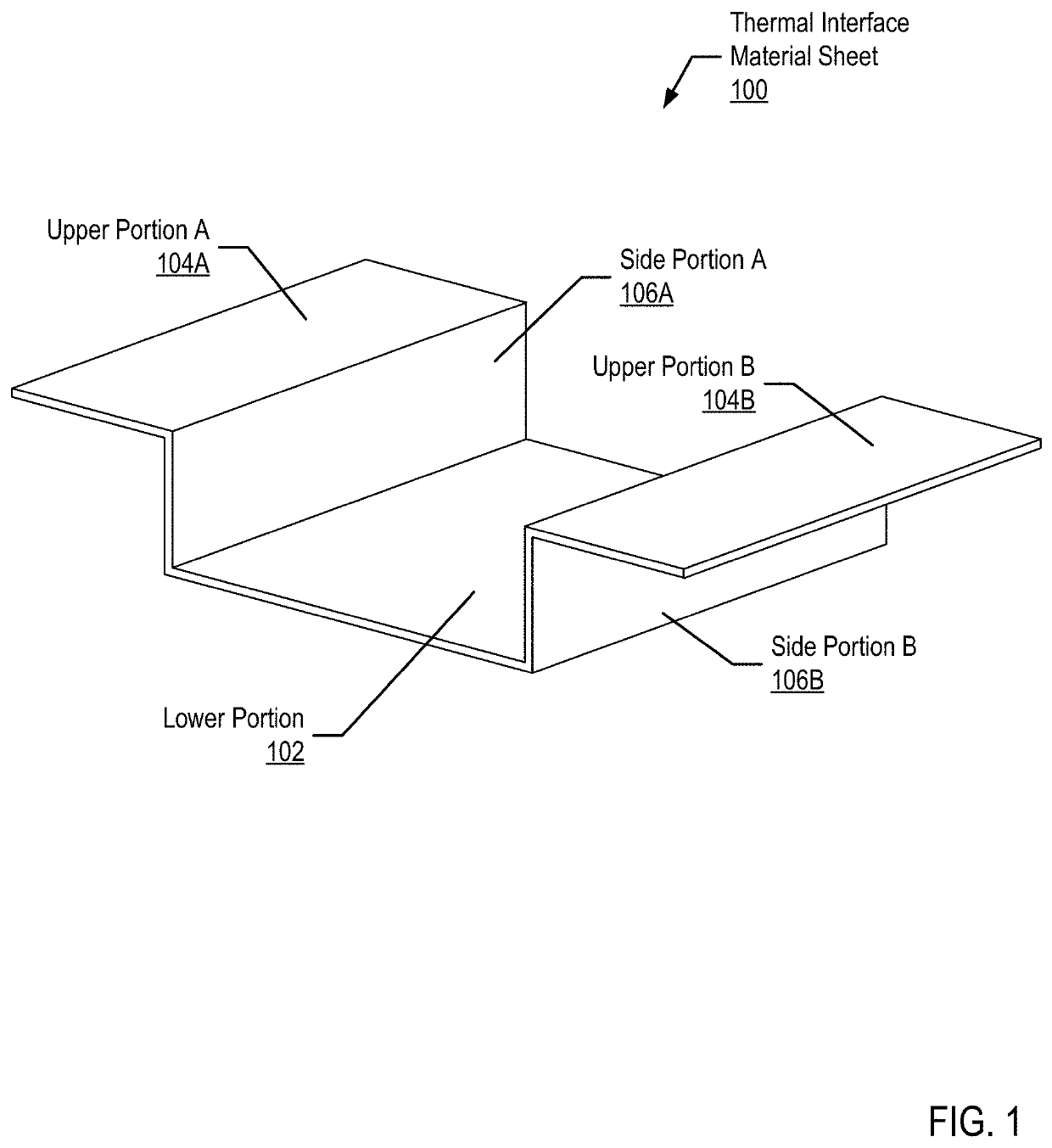
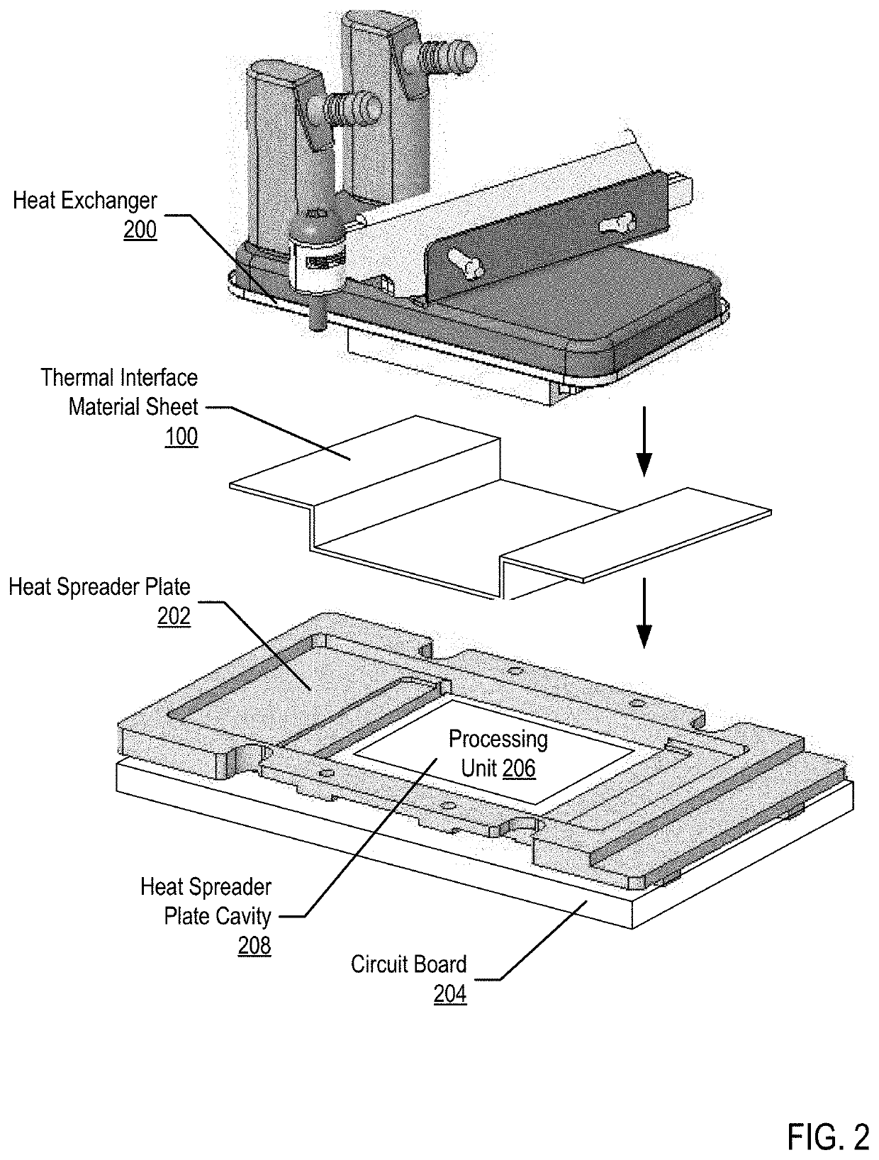
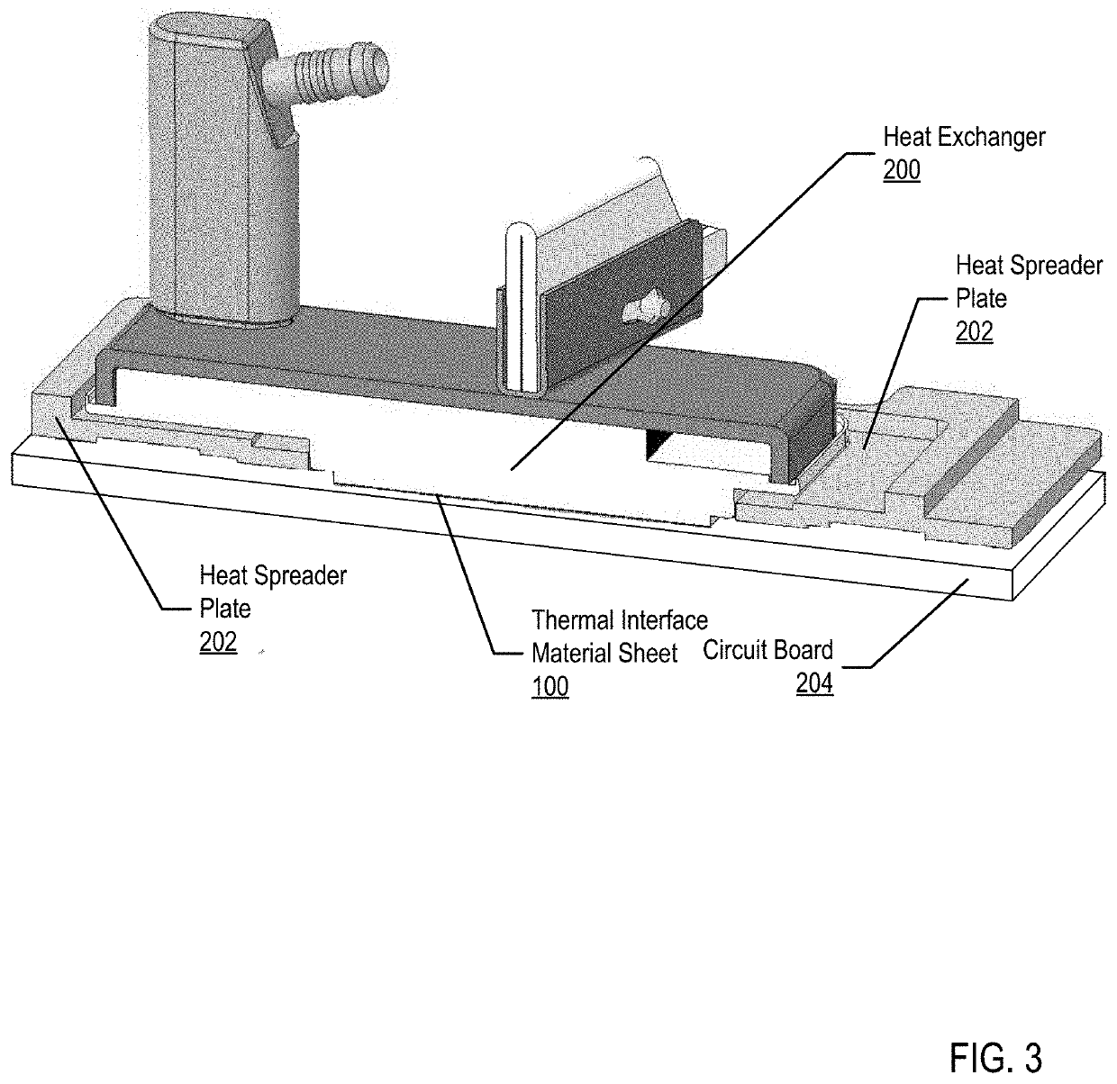
[0029]FIG. 1 sets forth a diagram depicting an example thermal interface material (TIM) sheet for directing heat in a three-dimensional space according to embodiments of the present invention. As shown in FIG. 1, the TIM sheet (100) includes a lower portion (102), two upper portions (upper portion A (104A), upper portion B (104B)), and two side portions (side portion A (106A), side portion B (106B)).

[0030]The TIM sheet (100) is a single, continuous sheet of thermal conducting material. The TIM sheet may be a single material type, such as a graphite TIM sheet. Alternatively, the TIM sheet may be a composite material, such as a particle or fiber filled silicone and / or acrylate TIM sheet. Additionally, the TIM sheet may be a cured or partially cured elastomer matrix, such as silicone, filled with any number of thermally conductive materials. Such thermally conductive materials may include ceramic particles such as, but not limited to, aluminum nitride, boron, nitride, zinc oxide, or al...


PUM


Abstract

A thermal interface material (TIM) structure for directing heat in a three-dimensional space including a TIM sheet. The TIM sheet includes a lower portion along a lower plane; a first side portion along a first side plane; a first upper portion along an upper plane; a first fold between the lower portion and the first side portion positioning the first side portion substantially perpendicular to the lower portion; and a second fold between the first side portion and the first upper portion positioning the first upper portion substantially perpendicular to the first side portion and substantially parallel to the lower portion.

Description

BACKGROUNDField of the Invention[0001]The field of the invention is data processing, or, more specifically, methods and system for thermal interface material structures for directing heat in a three-dimensional space.Description Of Related Art[0002]The development of the EDVAC computer system of 1948 is often cited as the beginning of the computer era. Since that time, computer systems have evolved into extremely complicated devices. Today's computers are much more sophisticated than early systems such as the EDVAC. Computer systems typically include a combination of hardware and software components, application programs, operating systems, processors, buses, memory, input / output devices, and so on. As advances in semiconductor processing and computer architecture push the performance of the computer higher and higher, more sophisticated computer software has evolved to take advantage of the higher performance of the hardware, resulting in computer systems today that are much more p...

Claims


Application Information

Patent Timeline
IPC IPC(8): G06F1/20H05K7/20
CPCG06F1/20H05K7/20481H01L21/4878H01L23/3737H01L23/373H01L23/433H01L23/473H01L23/4006
Inventor HOFFMEYER, MARK K.MARROQUIN, CHRISTOPHER M.CAMPBELL, ERIC J.CZAPLEWSKI-CAMPBELL, SARAH K.MANN, PHILLIP V.
Owner IBM CORP
Learn More