Integrated power generation system

a power generation system and integrated technology, applied in the direction of electrochemical generators, electrical apparatus, fuel cells, etc., can solve the problems of catastrophic damage ingestion of combustion products into the sofc stack at higher operating temperatures, the stack design of conventional metal interconnects tends to material degradation at these higher operating temperatures, and the average pressure of elevated pressure of conventional sofc stacks, etc., to achieve improved overall electric efficiency, reduce waste heat loss to the environment, and improve fuel energy density

Pending Publication Date: 2021-12-09
PRECISION COMBUSTION
View PDF0 Cites 2 Cited by
  • Summary
  • Abstract
  • Description
  • Claims
  • Application Information

AI Technical Summary

Benefits of technology

[0025]The system apparatus and process of this invention provide for a power generation system of improved overall electric efficiency through recuperation of SOFC stack and combustor waste heat and through reduced losses of waste heat to the environment. One enabler of this invention is its thermal integration of a unique steam reformer with the SOFC stack(s). Another enabler of this invention is its design for cycling the anode waste gas stream to the combustor, as opposed to prior art recycling of the anode waste gas stream to the steam reformer. Yet another enabler of this invention is incorporation of a condenser between the anode side of the SOFC stack(s) and the combustor, such that the first anode waste gas stream is passed to the condenser where at least a fraction of the water is removed, thereby resulting in a second anode waste gas stream of higher fuel energy density and reduced water content. This second anode waste gas stream and at least a portion of the cathode waste gas are then passed into the combustor where combustion occurs with release of exothermic heat. The water stream obtained from the condenser is converted to steam or superheated steam in a heater that obtains its heat via recuperation of stack heat and the exotherm from the combustor. Water has a higher heat capacity than air. By moving the heat into the water or into a low temperature steam feed, the heater and any other heat exchangers are kept at a more compact and efficient size, as compared with prior art systems. Moreover, the waste heat is then used efficiently to create a hotter steam for the endothermic reforming process, as opposed to prior art that uses essentially all of such heat to make a hotter cathode air for the already exothermic fuel cell process.

Problems solved by technology

Still, conventional SOFC stacks typically cannot survive elevated pressures, because seals and ceramic cells tend towards damage and failure as pressure differentials increase.
Second, to maximize thermal efficiency, the SOFC stacks are likely to operate at an upper end of the operable temperature range, specifically, between about 600° C. to 900° C. SOFC stacks designed with conventional metal interconnects tend towards material degradation at these higher operating temperatures.
Present day turbomachinery often exhibit flow reversal resulting in ingestion of combustion products into the SOFC stacks with catastrophic damage.

Method used


Image

  • Integrated power generation system
  • Integrated power generation system
  • Integrated power generation system

Examples


embodiment 100

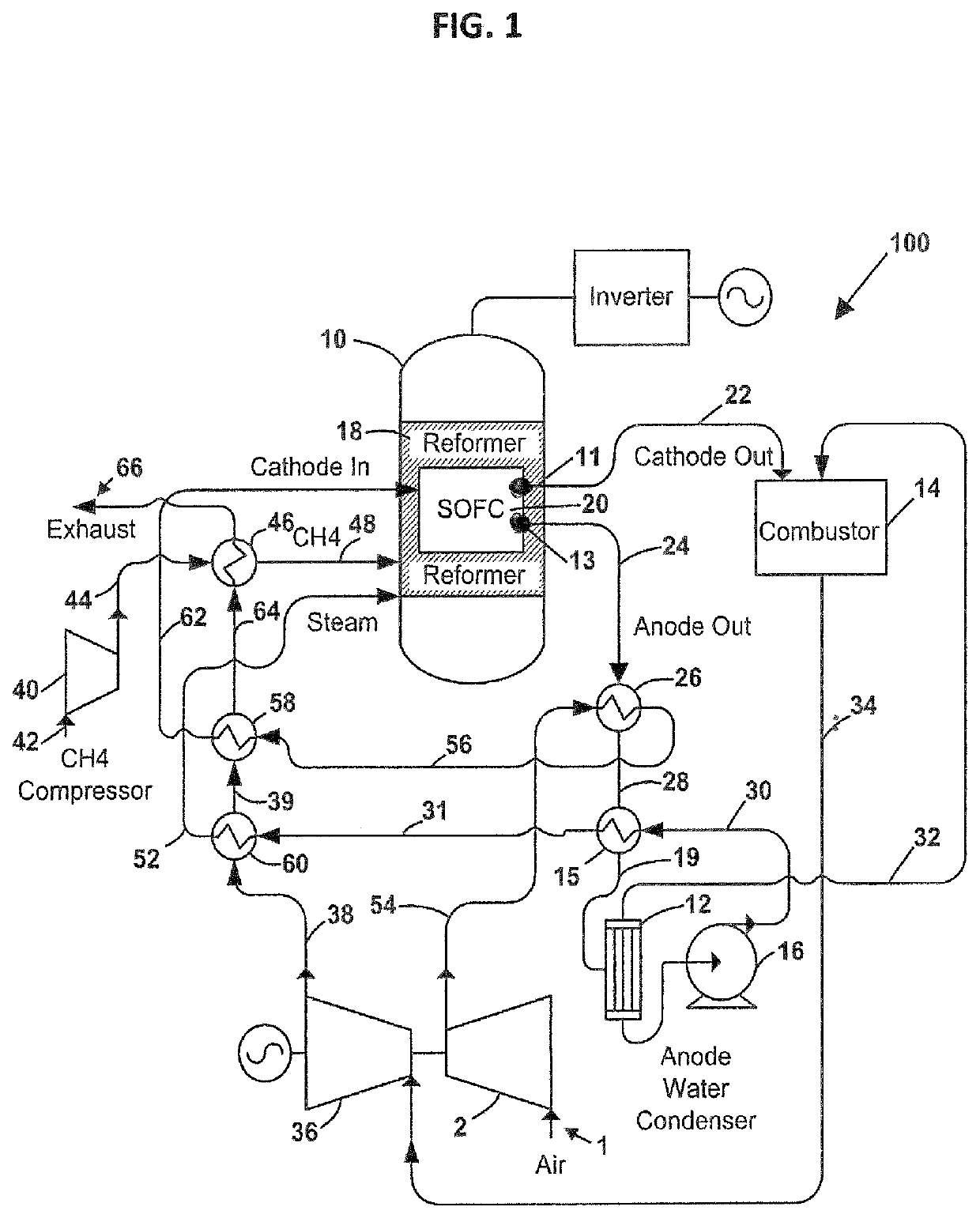
[0043]With reference to FIG. 1, a schematic is depicted of an embodiment 100 of the thermally integrated power generation system of this invention. As seen in FIG. 1, a hotbox 10 houses a steam reformer 18 and at least one SOFC stack 20. The spatial and thermal relationships of the steam reformer 18 to the at least one SOFC stack 20 are not illustrated in FIG. 1. Any conventional arrangement of these components is acceptable as known in the art. A hydrocarbon fuel inlet line 42 fluidly connects to a fuel compressor 40, from which compressed hydrocarbon fuel line 44 exits. The compressed hydrocarbon fuel line 44 passes into a reformer fuel preheat exchanger 46 from which hot compressed fuel line 48 exits and fluidly connects to the steam reformer 18. A steam inlet line 52 also connects to the steam reformer 18. A reformate output line (not shown) connects the steam reformer 18 with the anode (fuel electrode) side 13 of the SOFC stack 20.

[0044]Further to FIG. 1, air (oxidant) line 1 i...

embodiment 200

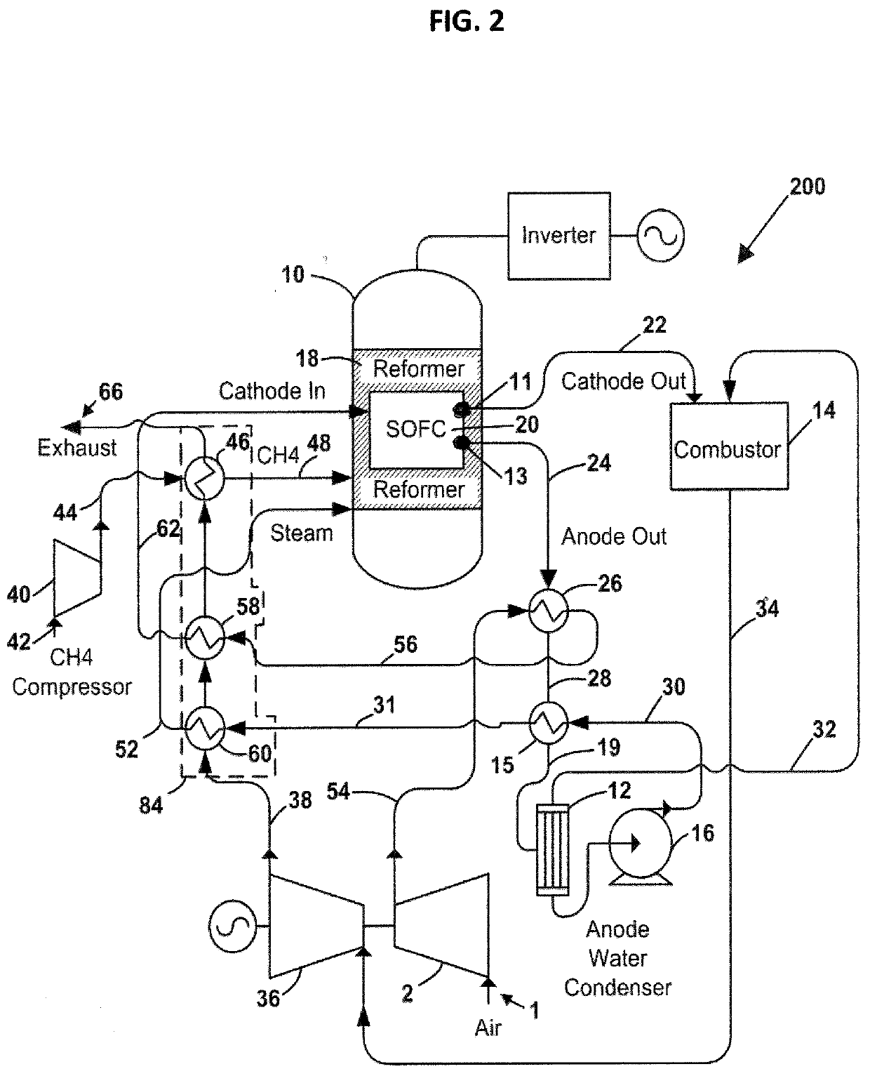
[0049]FIG. 2 depicts another embodiment 200 of the thermally integrated power generation system of this invention, which is similar in all respects to the embodiment depicted in FIG. 1 with one exception. In FIG. 2, the heater 60, the cathode air preheat exchanger 58, and the reformer fuel heat exchanger 46 are all combined into a multi-line heat exchanger 84 encircled by dotted lines in FIG. 2. As such, the expanded combustion product line 38 passes into the hot side of the multi-line heat exchanger 84; while each of the water / steam line 31, the cathode air line 56, and the reformer fuel line 44 passes individually through the cool side of the multi-line heat exchanger 84.

[0050]Functionally, as implied from FIG. 2, thermal energy in the combustion products flowing in expanded combustion product line 38 converts water flowing directly from line 30 (or water and / or steam flowing in line 31) into steam, which steam is fed through steam line 52 to the reformer 18. Likewise, thermal ene...


PUM

PropertyMeasurementUnit
channel lengthaaaaaaaaaa
temperatureaaaaaaaaaa
lengthaaaaaaaaaa

Abstract

An integrated power generation system including: a hotbox containing a steam reformer and at least one solid oxide fuel cell (SOFC) stack; a condenser, a combustor, a heater, and a turbomachine comprising a compressor and an expander. The steam reformer is configured to convert a hydrocarbon fuel and steam into a stack fuel. The SOFC stack is configured to convert the stack fuel into a first anode waste gas. The condenser functions to remove water from the first anode waste gas, thereby producing a second anode waste gas of higher fuel energy density. The combustor bums the second anode waste gas with release of exothermic heat. The heater thermally transmits heat from an expanded combustion product to water collected in the condenser, so as to generate steam. A steam line fluidly connects the heater to the steam reformer.

Description

CROSS-REFERENCE TO RELATED APPLICATION[0001]This application claims benefit of provisional patent application No. 62 / 760,979, filed Nov. 14, 2018.FIELD OF THE INVENTION[0002]This invention pertains to a power generation system.BACKGROUND OF THE INVENTION[0003]A need exists in the art for an improved power generation system for distributed energy markets. As intended for this invention, the power generation system includes at least a combustor, a turbomachine, and a solid oxide fuel cell hotbox comprising a housing within which are disposed a steam reformer and at least one solid oxide fuel cell (SOFC) stack.[0004]As background review, the steam reformer functions to convert a mixture of hydrocarbon fuel and steam in an endothermic process into a partially oxidized reformate comprising hydrogen and carbon monoxide, which is useful as a stack fuel. The SOFC stack is constructed of a plurality of SOFC repeat units, each repeat unit comprising a fuel electrode (anode), a solid oxide ele...

Claims


Application Information

Patent Timeline
Patent Type & Authority Applications(United States)
IPC IPC(8): H01M8/0612H01M8/04111H01M8/04014H01M8/04119
CPCH01M8/0618H01M8/04111H01M2008/1293H01M8/04156H01M8/04022H01M8/04014Y02E60/50
Inventor ROYCHOUDHURY, SUBIRLABRECHE, TIMOTHYVILEKAR, SAURABHQI, CHUNMING
Owner PRECISION COMBUSTION
Why Eureka
Try Eureka