Bubble ejection method, bubble ejecting device, and bubble ejection apparatus

a technology of ejecting device and bubble, which is applied in the direction of gas handling apparatus, biomass after-treatment, microinjection based, etc., can solve the problems of continuous processing, high degradability processing difficulty, and limit in improving the permeability of the cell membrane, so as to achieve the effect of improving the usability of the ejecting device when the bubble ejection method is implemented and easy production

Pending Publication Date: 2021-12-23
KYUSHU UNIV
View PDF0 Cites 0 Cited by
  • Summary
  • Abstract
  • Description
  • Claims
  • Application Information

AI Technical Summary

Benefits of technology

[0038]The bubble ejecting device disclosed in the present application can be easily produced by forming a bubble ejection hole in a substrate formed of a dielectric so as to penetrate the substrate. Further, since the bubble ejection hole is formed so as to penetrate the substrate, a bubble is ejected from the surface of the substrate. Thus, unlike the conventional bubble ejection port, the bubble ejection hole is less likely to break. Therefore, usability in handling the bubble ejecting device when the bubble ejection method is implemented is improved.

Problems solved by technology

In a conventional contact processing technology using a probe such as an electrical scalpel, however, there are problems that (1) because of a nature of burning off a target by Joule heat generated at a continuous high frequency, a peripheral tissue is much affected by roughness of the cut surface and heat invasion due to heat, in particular, the cut surface is much damaged by heat in a case of processing of a biomaterial in a liquid phase, (2) protein denaturation or amide bound fragmentation causes difficulty in recombination or regeneration, and (3) further in the continuous processing, adsorption of heat-denatured proteins or the like or adsorption of bubbles generated due to heat to the probe significantly deteriorates an observation environment of an incision surface, which makes high degradability processing difficult.
Further, also in a contactless processing technology using laser such as femtosecond laser, there is a problem of difficulty in continuous processing or the like because locally spotted high-density energy causes the heat to affect the tissue around a cut surface and, in particular, because of generation of bubbles or the like due to heat generated at processing in a case of processing of a target in a liquid phase.
In the conventional electroporation technology, however, there is a limit in improving permeability of a cell membrane by changing the electric field intensity, and there are problems of difficulty in injection to a target having a hard cell membrane or a cell wall instead of soft fatty double membranes, difficulty in local injection to an intended place due to restriction of the arrangement of electrodes or the like, and the like.
Further, in the sonoporation technology using ultrasonic waves, there are problems of difficulty in convergence of ultrasonic waves, difficulty in generating local cavitation of bubbles to increase resolution, and the like.
Furthermore, in an injection method with the particle gun method, there is a problem of low introduction efficiency or the like because substances attached to particle surfaces are detached from the surfaces when particles are injected.

Method used


Image

  • Bubble ejection method, bubble ejecting device, and bubble ejection apparatus
  • Bubble ejection method, bubble ejecting device, and bubble ejection apparatus
  • Bubble ejection method, bubble ejecting device, and bubble ejection apparatus

Examples


first embodiment

of Device

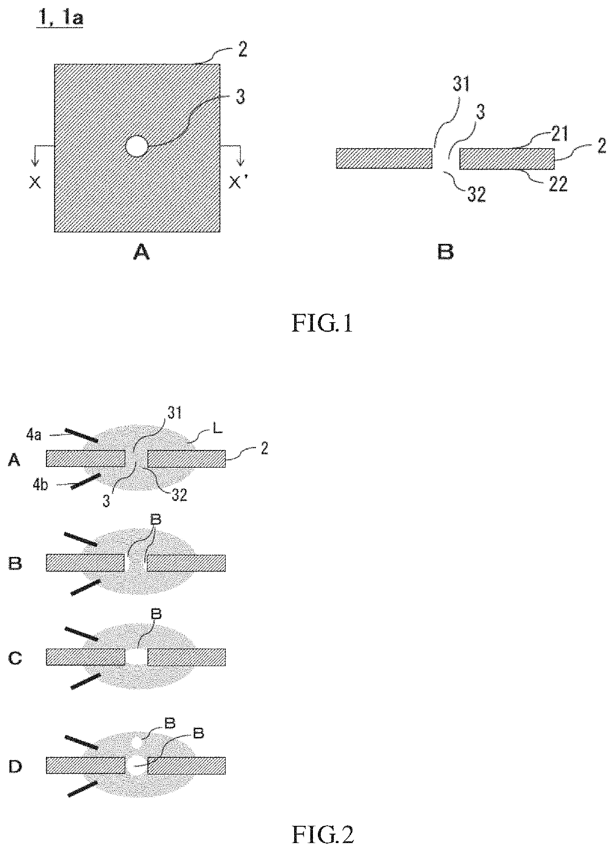
[0057]A device 1a according to a first embodiment will be described with reference to FIG. 1. FIG. 1A is a top view of the device 1a, and FIG. 1B is a sectional view taken along a line X-X′ of FIG. 1A. The device 1a includes a substrate 2 formed of a dielectric and a bubble ejection hole 3. The bubble ejection hole 3 is formed so as to penetrate through a first face 21 and a second face 22, which is a face opposite to the first face 21, of the substrate 2, a first opening 31 is formed in the first face 21, and a second opening 32 is formed in the second face 22.

[0058]Before describing the configuration of the device 1a in detail, the principle of how a bubble is ejected by using the device 1a will be described first. FIG. 2A to FIG. 2D are schematic sectional views illustrating the principle of how a bubble B is ejected. Note that, since the components of the device 1a are the same in these four drawings, denotation of references other than the bubble B is omitted in FIG. 2...

second embodiment

of Device

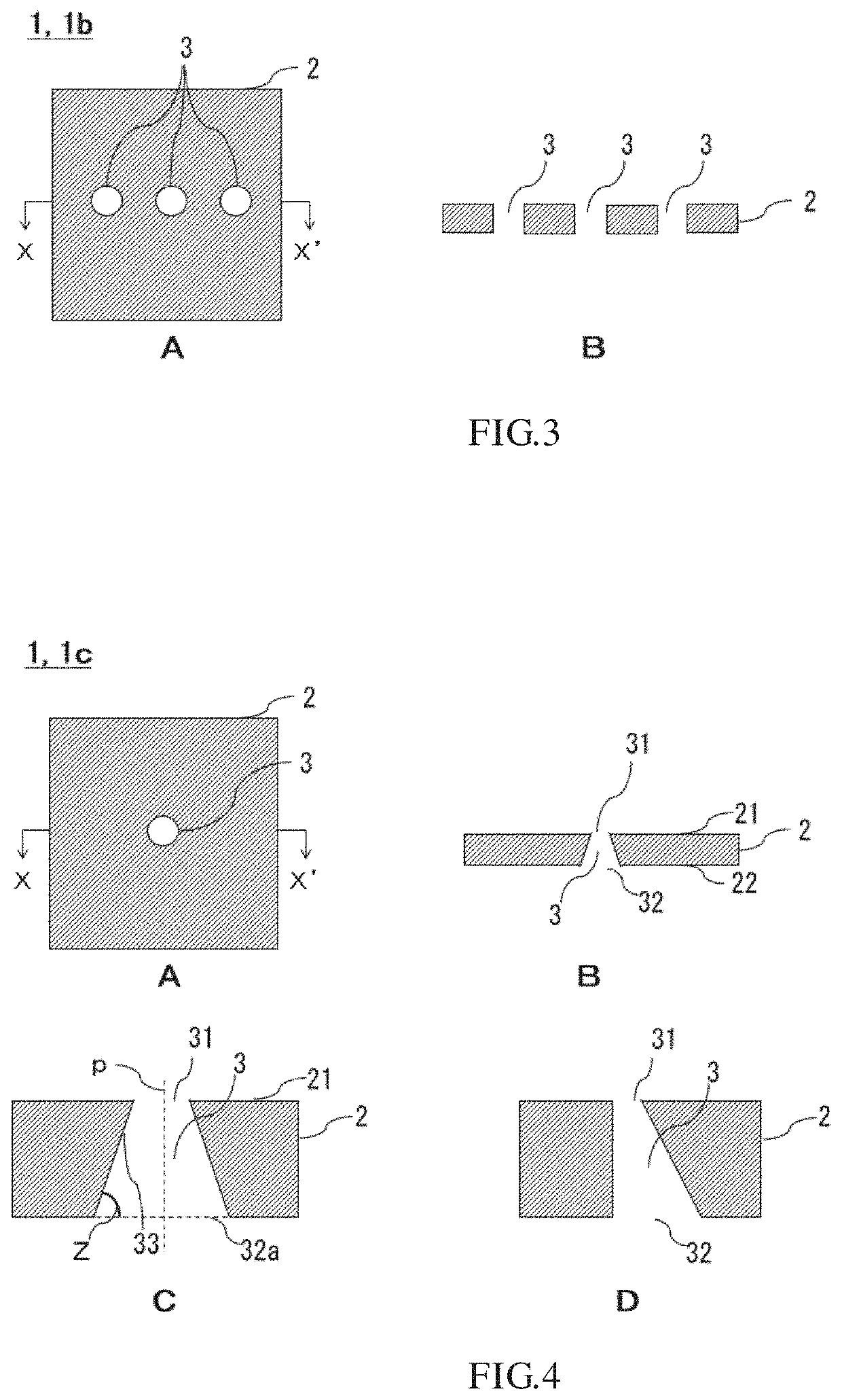
[0067]Next, a device 1b according to a second embodiment will be described with reference to FIG. 3. FIG. 3A is a top view of the device 1b, and FIG. 3B is a sectional view taken along a line X-X′ of FIG. 3A. The device 1b is different from the device 1a according to the first embodiment in that at least two bubble ejection holes 3 are formed and is the same as the device 1a with respect to other features. Note that, although an example in which the three bubble ejection holes 3 are arranged in series is illustrated in FIG. 3A and FIG. 3B, the number of bubble ejection holes 3 is not limited, and the arrangement of the bubble ejection hole 3 can be determined as appropriate in accordance with the purpose. With a use of the device 1b, bubbles can be ejected to different positions on a processing target at the same time.

[0068]Note that Patent Literature 2 discloses that a plurality of bubble ejection portions are formed and bubbles are ejected to different positions on a proc...

third embodiment

of Device

[0069]Next, a device 1c according to a third embodiment will be described with reference to FIG. 4. FIG. 4A is a top view of the device 1c, and FIG. 4B is a sectional view taken along a line X-X′ of FIG. 4A. The device 1c differs from the device 1a according to the first embodiment in that the device 1c is produced so that the first opening 31 and the second opening 32 have different sizes. Note that, in the present specification, the term “size” means a diameter in a case of a circle or a diameter of a circumscribed circle in a case of a shape other than a circle. Although the size of the first opening 31 is smaller than the size of the second opening 32 in the example illustrated in FIG. 4B, the size of the first opening 31 may be larger than the size of the second opening 32. Note that, in the present specification, the bubble ejection hole 3 formed such that the first opening 31 and the second opening 32 have different sizes may be referred to as “tapered” one. Further,...


PUM

PropertyMeasurementUnit
dielectric strengthaaaaaaaaaa
voltageaaaaaaaaaa
voltageaaaaaaaaaa

Abstract

The present invention addresses the problem of providing a bubble ejection method based on a new principle that is different from conventional bubble ejection methods and a bubble ejecting device.To solve the problem, provided is a bubble ejection method using a bubble ejecting device, wherein the bubble ejecting device comprisesa substrate formed of a dielectric,at least one bubble ejection hole formed so as to penetrate through a first face and a second face, which is a face opposite to the first face, of the substrate,a first opening formed at a position of the first face at which the bubble ejection hole penetrates, anda second opening formed at a position of the second face at which the bubble ejection hole penetrates,the bubble ejection method comprising:a substrate-conductive liquid contact step;a conductive liquid-electrode contact step;a voltage application step; anda bubble ejection step.

Description

TECHNICAL FIELD[0001]The present disclosure in the present application relates to a bubble ejection method, a bubble ejecting device, and a bubble ejection apparatus.BACKGROUND ART[0002]Due to progress of biotechnology in recent years, there is a growing demand for local processing of a cell or the like, such as processing to perforate a membrane or a wall of a cell and remove a nucleus from the cell or introduce a nucleic acid substance such as DNA to the cell. As a local processing technology (hereafter, also referred to as “local ablation method”), methods using a contact processing technology using a probe such as an electrical scalpel, a contactless ablation technology using laser or the like, or the like are widely known.[0003]In a conventional contact processing technology using a probe such as an electrical scalpel, however, there are problems that (1) because of a nature of burning off a target by Joule heat generated at a continuous high frequency, a peripheral tissue is m...

Claims


Application Information

Patent Timeline
Patent Type & Authority Applications(United States)
IPC IPC(8): C12N15/89C12M1/00B01L5/00
CPCC12N15/895B01L2400/0442B01L5/00C12M47/06C12M35/04C12M35/02C12M23/26C12N15/87
Inventor YAMANISHI, YOKOYAMASHITA, YUICHIKAWA, KEITAFUKUYAMA, YUDAIMASUDA, REN
Owner KYUSHU UNIV
Why Eureka
Try Eureka