Retractable Ion Guide, Grid Holder, and Technology for Removal of Cryogenic Sample from Vacuum

a technology of ion guide and grid holder, which is applied in the direction of electric discharge tube, particle separator tube details, particle separator tube, etc., can solve the problems of destroying the required structural heterogeneity, generating only a very few particles, and significant problems

Pending Publication Date: 2022-07-14
WISCONSIN ALUMNI RES FOUND
View PDF3 Cites 0 Cited by
  • Summary
  • Abstract
  • Description
  • Claims
  • Application Information

AI Technical Summary

Problems solved by technology

Unfortunately, currently existing sample preparation techniques impart a non-random orientation of the particles (due largely to particle migration to the air/water interface), and the particles often become deformed/stretched at the air-water interface, thereby destroying the required structural heterogeneity.
However, this imposes a significant problem as the majority of the sample gets removed during the blotting process during conventional preparation techniques.
As a result, these samples yield only a very few particles per grid hole.
Second, formation of ice in conventional methods causes the ice at the center of a hole in the grid to be

Method used


Image

  • Retractable Ion Guide, Grid Holder, and Technology for Removal of Cryogenic Sample from Vacuum
  • Retractable Ion Guide, Grid Holder, and Technology for Removal of Cryogenic Sample from Vacuum
  • Retractable Ion Guide, Grid Holder, and Technology for Removal of Cryogenic Sample from Vacuum

Examples


example 1

lar Vapor Deposition

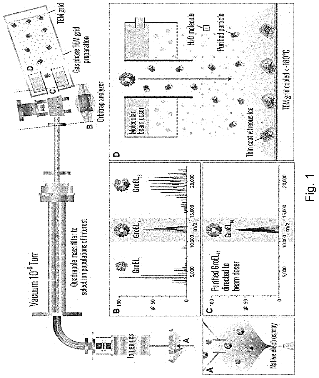
[0057]In biomolecular vapor deposition (BVD), a mass spectrometry (MS) device is utilized with cryo-EM gas phase sample preparation in order to purify proteins and protein complexes in the gas-phase for subsequent in vacuo vitrification. Samples prepared in this way can be extracted from the mass spectrometer using the cryo-transfer sample holder and placed directly into an EM for imaging.

[0058]Gas-phase biomolecule freezing prior to surface deposition may be especially useful for fragile or flexible molecules, allowing the molecules to retain their condensed phase shape by removing as much of their energy as possible before they contact the grid. A common practice in the field of gas-phase IR spectroscopy, freezing biomolecules in the gas-phase can be accomplished through the use of supersonic beams, decelerated beams, cooled or slowed buffer gases, or cryogenically cooled ion traps, amongst other methods (see Rijus and Oomens, “Gas-phase it spectroscopy and str...

example 2

le Ion Guide

[0062]In one example of a successful BVD method, several key steps are performed. Firstly, biomolecular ions are transported from a mass spectrometer to a TEM grid cryogenically cooled to −185° C. During the collection of the particles onto the TEM grid, water vapor is introduced into the vacuum for ice formation. Once deposition of particles and ice on the TEM grid is complete, the chamber containing the grid is raised to a pressure where nitrogen will not sublimate and remain a liquid at −190° C. While maintaining a temperature below −175° C., the TEM grid is evacuated from the chamber into a storage container or transported directly to a cryo-EM instrument.

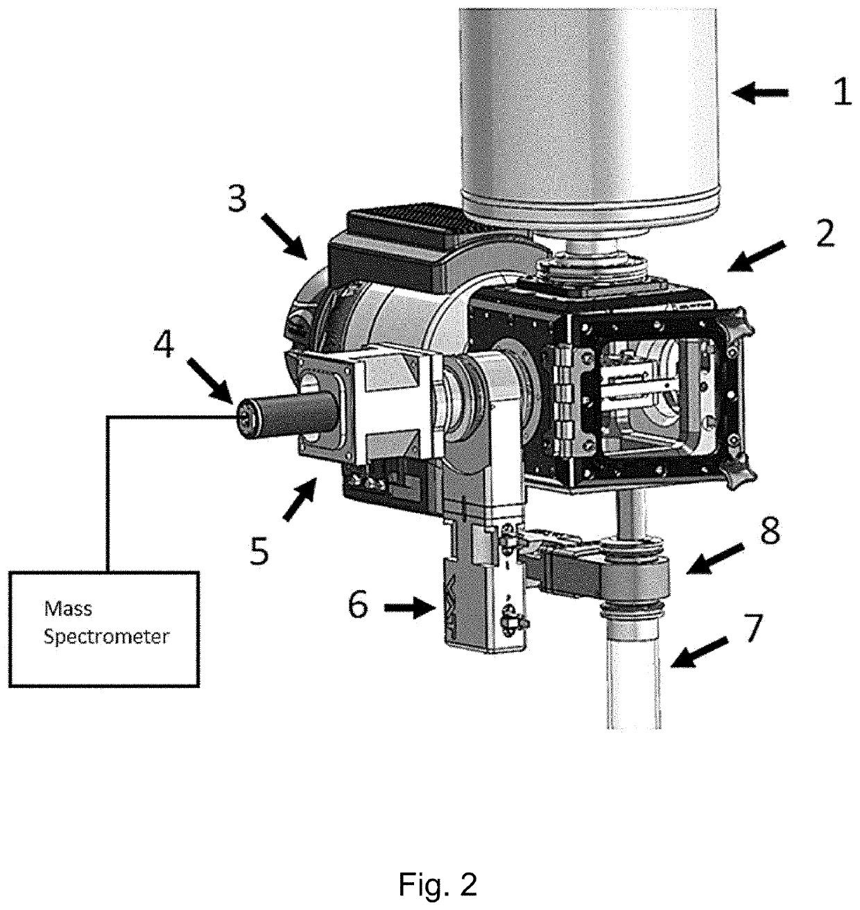
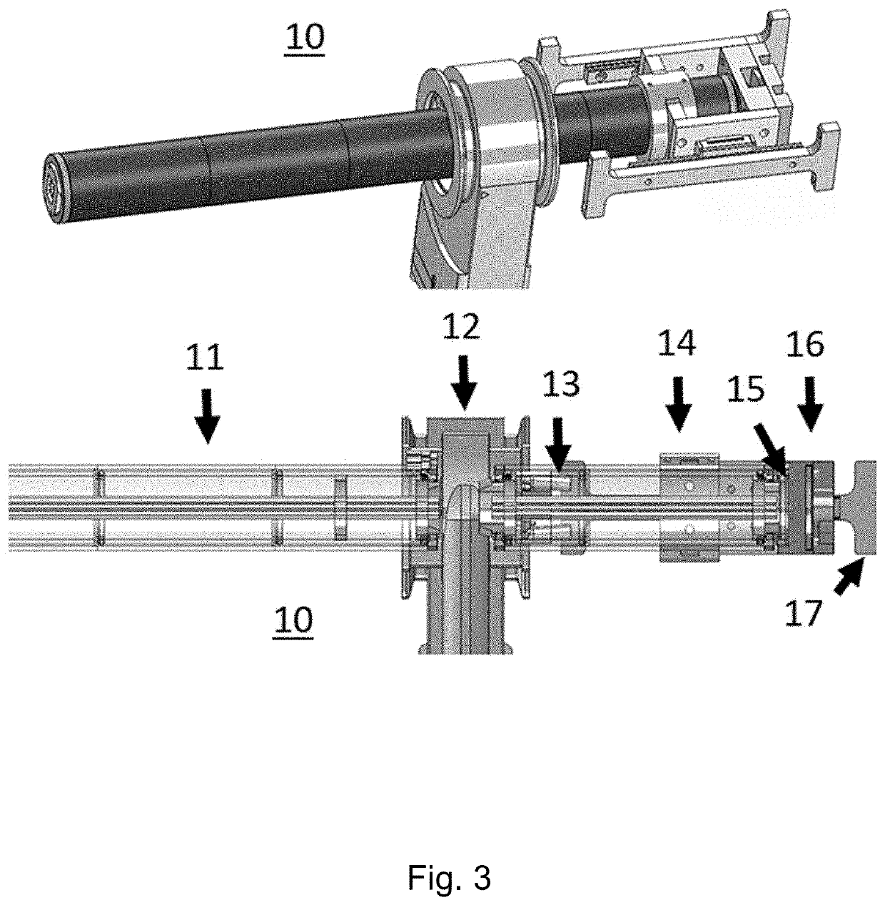
[0063]In this example, the instrument components used to remove the TEM grid are illustrated in FIGS. 2 and 3. The sample vacuum chamber 2 contains a chilling unit for the TEM grid which is cooled to −185° C. using circulating liquid nitrogen supplied by the large dewar 1. The sample vacuum chamber 2 is maintained a...

example 3

f the Grid from Vacuum

[0068]To remove a grid that has been prepared with amorphous ice and biomolecules according to the above examples, the grid is transported from a region of ultrahigh vacuum to an environment of liquid nitrogen without ever reaching a temperature greater than −170° C. or being exposed to water in the atmosphere. The removal process begins by retracting the grid ion guide 14 and cooling box 16 out of the path of the vacuum gate valve 12, at which point the vacuum gate valve 12 can be closed. The mass spectrometer vacuum region and sample vacuum chamber 2 are now effectively separated. To raise the pressure in the sample vacuum chamber 2, the vacuum pump 3 is switch off and pressure is elevated by pumping liquid nitrogen into this chamber.

[0069]While the pressure is low, the liquid nitrogen immediately turns into solid nitrogen which then sublimates into gaseous nitrogen. As the pressure elevates, the liquid nitrogen entering the sample vacuum chamber 2 remains in...


PUM


Abstract

Imaging by cryo-electron microscopy (cryo-EM) requires that a sample be encased in an amorphous solid, such as amorphous ice. In current cryo-EM preparation systems, once the sample has been deposited on an EM grid and coated in the amorphous solid, the EM grid must be removed from vacuum and then transferred into the vacuum of the cryo-EM system. As a result, samples deposited on the grid are exposed to damage and contamination. The present invention provides improved EM grid handling systems and devices compatible with advanced cryo-EM sample preparation techniques and which reduce or eliminate exposure of the sample on the grid to atmosphere and elevated temperatures. These methods and devices will also significantly reduce handling time and complexities associated with cryo-EM sample preparation.

Description

CROSS-REFERENCE TO RELATED APPLICATIONS[0001]This application claims the benefit of priority to U.S. Provisional Patent Application No. 63 / 136,857, filed Jan. 13, 2021, which is specifically incorporated by reference to the extent not inconsistent herewith.STATEMENT REGARDING FEDERALLY SPONSORED RESEARCH[0002]This invention was made with government support under GM118110 awarded by the National Institutes of Health. The government has certain rights in the invention.BACKGROUND OF THE INVENTION[0003]Mass spectrometry (MS) technologies are currently used to analyze, en masse, protein abundance, modification state, interaction partners, and even biochemical pathways in which proteins function. Native MS gently ionizes protein complexes using electrospray under conditions that preserve protein structure. Extremely accurate mass measurement of these mega-Dalton protein complexes allows for calculation of sub-unit stoichiometry and even identification of non-covalently bound small molecul...

Claims


Application Information

Patent Timeline
IPC IPC(8): H01J49/00H01J49/04H01J49/06G01N1/42
CPCH01J49/0004H01J49/0495G01N1/42H01J49/0486H01J49/062H01J2237/2007H01J49/04H01J49/0468
Inventor WESTPHALL, MICHAEL SCOTTCOON, JOSHUA JACQUES
Owner WISCONSIN ALUMNI RES FOUND
Why Eureka
Try Eureka