Water pipe protecting refractory structure

a technology of refractory structure and water pipe, which is applied in the direction of fuel injecting pump, machine/engine, lighting and heating apparatus, etc., can solve the problems of significant obstacle to heat transfer, extremely thick panel 104 with very low heat conductivity, and boilers with prior art design not being able to achieve maximum heat flow

Inactive Publication Date: 2000-01-11
MITSUBISHI HEAVY IND LTD
View PDF2 Cites 16 Cited by
  • Summary
  • Abstract
  • Description
  • Claims
  • Application Information

AI Technical Summary

Benefits of technology

As has been discussed above, with this invention a heat-resistant block is interlockingly secured to a boiler tube assembly by an interlocking attachment means whose two segments are provided on the surfaces of the block and tubes which face each other, and which allows the block to be attached (interlockingly secured) to or removed from the tube assembly. This interlocking attachment means may, for example, comprise a tapered tongue and recess which allow the block to be hung on the tube assembly taking advantage of the force of gravity to secure it, much as a picture is hung on a wall. This design dispenses with the bolt and nut used in the prior art, which were exposed to the combustion gases, and so prevents high-temperature corrosion from occurring.Because the block is mounted by means of interlocking attachment means which can become looser or tighter instead of a bolt and nut, it never becomes frozen to the tube assembly due to thermal expansion. The block can be made thinner, and the temperature differential between the inner and outer surfaces of the block is smaller than in prior art devices. Temperature spiking is controlled, and the resulting thermal stress on the block is reduced.The aforesaid heat-resistant block comprises a tubular shroud which conforms to the surface of the tube assembly. This design allows the block to be relatively thin and of a uniform thickness throughout. The block has high thermal conductivity and so can transfer thermal energy effectively to the tubes. It does not overheat and so does not experience a buildup of ash on the surface which is exposed to the combustion gases, as prior art blocks did. This block is thus able to maintain high thermal conductivity.With this invention, gases which cause high-temperature corrosion are effectively prevented from infiltrating the interlocking attachment means from the combustion gas chamber. In addition, the gap between the block and the tube assembly is uniform, so the layer of mortar which fills the gap cannot become excessively thick in any location.With this invention, the heat-resistant block can easily be mounted and removed. It is also easy to handle (i.e., to carry).

Problems solved by technology

This resulted in an extremely thick panel 104 with very low heat conductivity.
As a result, boilers with the prior art design were not able to achieve the maximum heat flow which is essential to boiler efficiency.
Because the heat transfer capability of this layer of ash is extremely inadequate, once ash 24 begins to adhere, the further melting and buildup of ash is promoted and the layer of insulation becomes thicker and thicker, posing a significant obstacle to heat transfer.
And because ash 24 contains corrosive components such as chlorine compounds, tubes 11 are exposed to high-temperature corrosion which may result in damage.
This stress and the thermal stress due to the temperature differential between the interior and exterior of block 26 may result in damage to the block.
If the corrosion is allowed to proceed, heat-resistant block 26 may be damaged or fall away from the boiler tubes.
The aforesaid prior art heat-resistant block pictured in FIG. 8 is relatively thick, and its thickness is not uniform.
For this reason it is liable to warp due to thermal stress.
Interlockingly securing the heat-resistant block to the tube assembly by forcing a tapered tongue into a tapered recess provides a simple mounting design which does not allow the block to draw away from the tubes.

Method used


Image

  • Water pipe protecting refractory structure
  • Water pipe protecting refractory structure
  • Water pipe protecting refractory structure

Examples


Embodiment Construction

In this section we shall discuss in detail two preferred embodiments of this invention with reference to the drawings. To the extent that the dimensions, material, shape or relative position of the structural components which are mentioned in these examples is not specifically disclosed, the invention is not limited only to the example given, which is meant merely for the purpose of illustration.

We shall first discuss a preferred embodiment of this invention with reference to FIGS. 1 through 4.

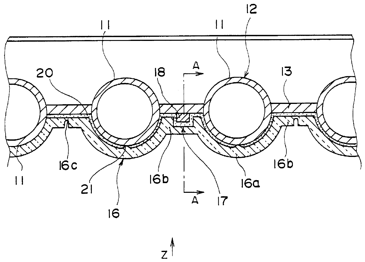
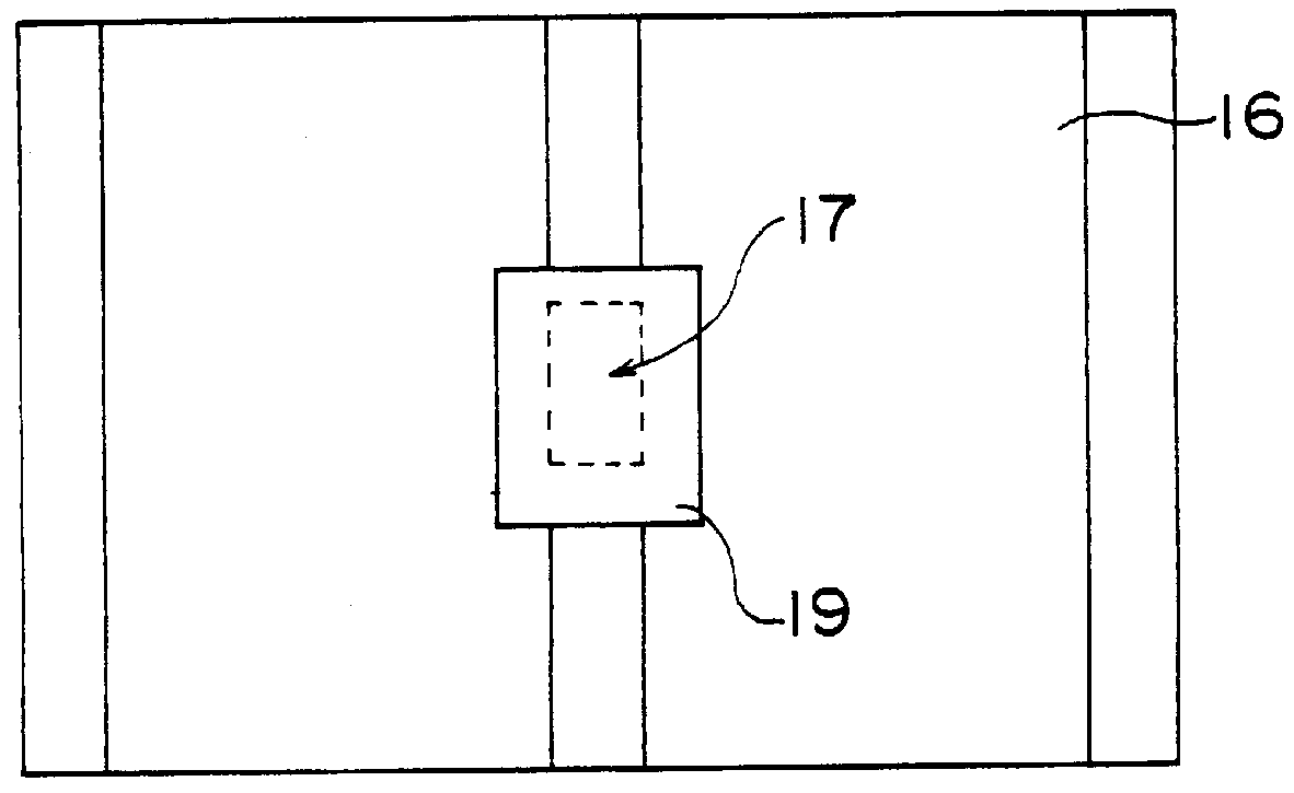
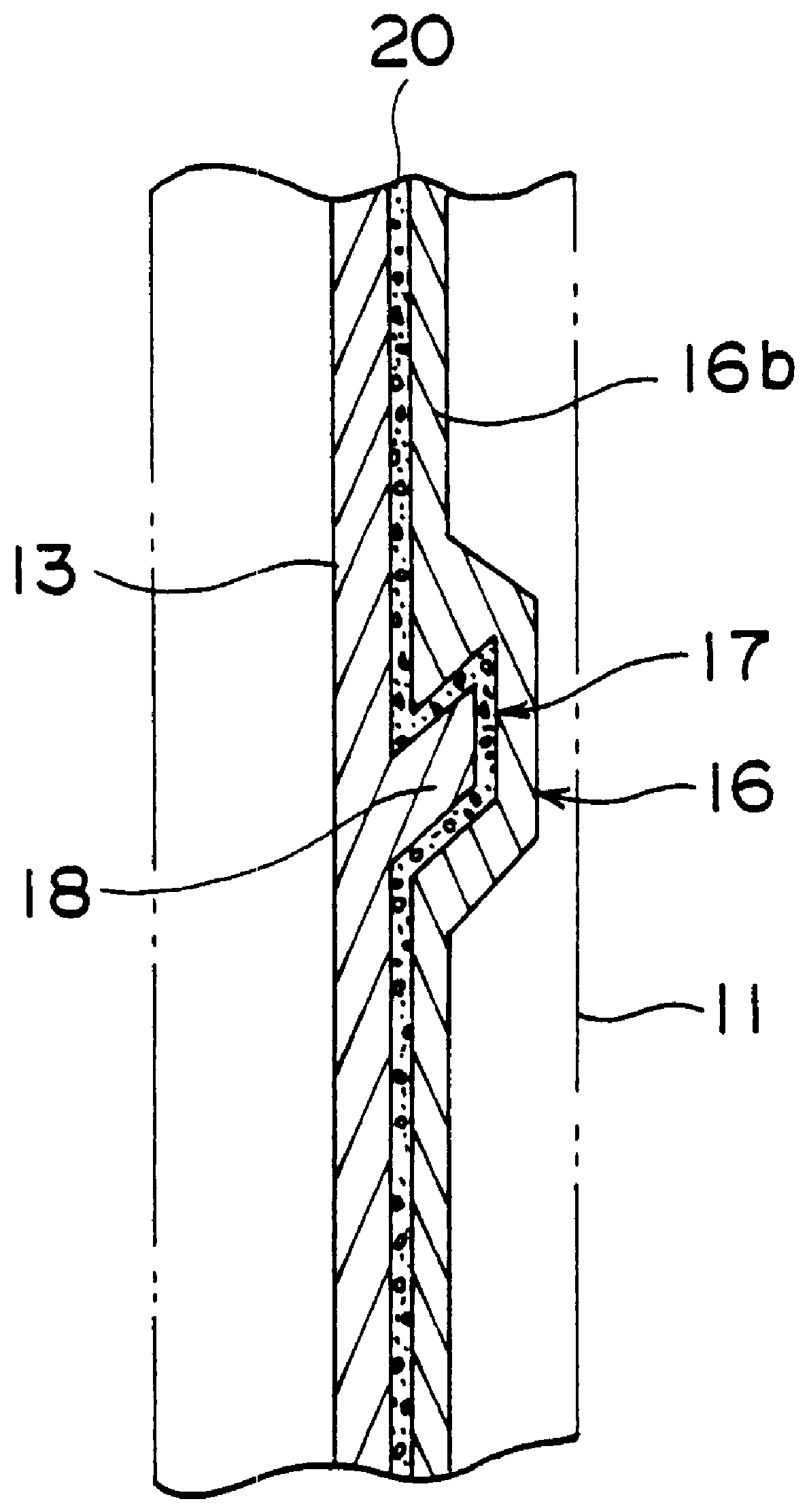
FIG. 1 is a horizontal cross section of a heat-resistant shield for the tubes in a waste heat boiler which is a first embodiment of this invention. FIG. 2 is a view of the shield in FIG. 1 as seen from the direction indicated by arrow Z. FIG. 3 is a cross section taken along line A--A in FIG. 1.

FIGS. 1 through 4 show cross sections of a combustion chamber for a boiler. This chamber is a high-temperature incinerator for garbage or industrial waste. 12 is the boiler tube assembly, which comprise...


PUM


Abstract

PCT No. PCT / JP97 / 02626 Sec. 371 Date Sep. 28, 1998 Sec. 102(e) Date Sep. 28, 1998 PCT Filed Jul. 29, 1997 PCT Pub. No. WO98 / 05901 PCT Pub. Date Dec. 2, 1998A heat-resistant assembly to shield boiler tubes which does not entail a thick heat-resistant block. This structure would be interposed between the boiler tubes and the combustion gases. Such a structure would be distinguished by the fact that it comprises heat-resistant block 16, itself composed of curved portion 16a, whose inner surface at one point comes in contact with the aforesaid boiler tube 11, and connecting portions 16b, and the aforesaid boiler tube assembly 12. The interlocking attachment structure which interlockingly secures these two components together in such a way that the block can be mounted or removed comprises recess 17, 58 or 68 and tongue 18, 59 or 69.

Description

This invention concerns a heat-resistant assembly for the tubes in a boiler such as a waste heat boiler which uses the heat from a garbage incinerator. More specifically, it concerns a heat-resistant design for a block of boiler tubes in a plant which obtains steam energy from a boiler using the exhaust gas from combusting garbage or industrial waste.TECHNICAL BACKGROUNDHeat-resistant structures for protecting boiler tubes in waste heat boilers are well known in the prior art. For example, in Patent Publication 2-203194, as is shown in FIG. 9, boiler tubes 101 are connected by fins 102 to form tube walls 100. Panels 104 are constructed of heat-resistant brick. The areas between the upper surfaces of panels 104 and the surfaces of tube walls 100 which face towards the gas and the areas between each pair of adjacent tubes are filled with mortar 107. The panels are fixed to tube walls 100 by means of stud bolt 103. The end of the aforesaid stud bolt 103 which is exposed is covered by c...

Claims


Application Information

Patent Timeline
Patent Type & Authority Patents(United States)
IPC IPC(8): F23M5/08F22B37/10F22B37/00F23M5/00F23M5/04
CPCF22B37/107F22B37/108F23M5/04F23M5/08Y10S122/13
Inventor ORITA, NORIHIKONAKAGAWA, YUJITAKAISHI, TAKEOTAKAHASHI, TETSUOGOTO, CHUHACHIKAWAHARA, YUZOIKE, MINORUTERASHIMA, YASUHIROINOUE, KEITA
Owner MITSUBISHI HEAVY IND LTD
Why Eureka
Try Eureka