Duplex coated steel composite products and method of manufacturing them

a composite product and duplex coating technology, applied in the direction of solid state diffusion coating, superimposed coating process, transportation and packaging, etc., can solve the problems of reducing wear resistance, easy oxidation, and defective nitrides such as tin, so as to prevent film oxidative degradation, improve performance, and reduce the effect of oxidation resistan

Inactive Publication Date: 2000-09-12
SUMITOMO METAL MINING CO LTD
View PDF3 Cites 27 Cited by
  • Summary
  • Abstract
  • Description
  • Claims
  • Application Information

AI Technical Summary

Benefits of technology

In view of the foregoing problems, it is an object of the present invention to provide duplex coated steel composite products by uniformly applying plasma nitriding on the entire surface of metal parts of different shapes simultaneously or while keeping the surface state of the metal parts, and subsequently forming a hard film continuously by a PVD method in an identical or separate apparatus, thereby forming a hard film having high adhesion and durability on the surface of the metal parts, as well as a method of manufacturing such duplex coated steel composite products.
Since the elastic deformation or plastic deformation on the surface of the substrate is substantially suppressed by a duplex coating of disposing the nitrided layer as the first layer on the surface of the substrate on which a hard film is formed as the second layer, destruction of the hard film due to incapability of following after the elastic deformation and plastic deformation can be prevented, to improve the durability such as wear resistance of the film.

Problems solved by technology

However, metal nitrides such as TiN are defective in that they are easily oxidized at high temperatures and their wear resistance is remarkably lowered owing to the brittle oxide layer formed by oxidation.
Therefore, no sufficient effects have been obtained in tools for working hard steel materials or hardly cuttable materials and molds for hot working.
The above mentioned TiAlN film has improved resistance due to addition of Al, but has a problem in that the mechanical characteristics of the film are worsened as the amount of Al increases.
Therefore, when the film is applied to tools, it worsens the quality of them.
Since Al is added essentially as a sort of defects in the TiN film, the TiAlN film suffers from lowering of the toughness and has poor mechanical characteristic compared with TiN.
A TiAiN film with an amount of Al of less than 10% exhibits a mechanical characteristic similar with that of a TiN film, but no substantial effect can be obtained for oxidation resistance by the addition of Al at such a low concentration.
In the plasma nitriding of the prior art, if metal parts having fine slits, apertures or grooves, or metal parts of different shapes are subjected to plasma nitriding simultaneously, since plasma are localized to specified portions of the metal member, to make the distribution of plasma not uniform, plasma nitriding is not applied uniformly on the surface of the metal parts, or local overheating occurs to abnormally raise the temperature on the surface of the metal parts, thereby deteriorating the characteristic of the parts.
Accordingly, it is impossible to apply uniform nitriding to the surface of the metal parts and, even if a hard film is formed by a PVD method on the metal parts that were subjected to not uniform nitriding, adhesion or durability of the film varies greatly.
However, when a nitrided layer (diffusion layer) of about 30 to 500 .mu.m thickness is formed to the metal parts by the existent plasma nitriding of the prior art, the surface roughness of the metal parts is increased by sputtering, fine powder caused by sputtering or the like is deposited, or a brittle compound layer is formed.
Then, when the film is formed over them, adhesion of the film is deteriorated and the adhesion or durability of the hard film formed after the plasma nitriding can not be improved but, rather, the characteristics of the hard film are worsened.

Method used


Image

  • Duplex coated steel composite products and method of manufacturing them

Examples


example 2

Plasma nitriding was conducted in the same manner as in Example 1 for 30 min using drills made of SKH 51 high speed tool steels. Th depth of the hardened layer was about 50 .mu.m. The drills were placed in a cathode arc type ion plating apparatus provided with a Ti cathode and, after evacuating the inside of the reaction chamber to 10.sup.-5 Torr, a bais voltage at -1000 V was applied to the drills and arc discharge was generated by the Ti cathode. The arc discharging current was 70 A. Then, arc discharging was continued for 2 min while monitoring the temperature at the surface of the substrate by IR emission thermometer, Ti was vaporized and ionized to conduct sputter cleaning for the surface of the drills. Elevation of the temperature up to the maximum 450.degree. C. at the surface of the drills was recognized during arc discharge.

Successively, application of the voltage to the Ti cathode was interrupted, and a bias voltage at -400 V was applied to the drills while causing a gas m...

example 3

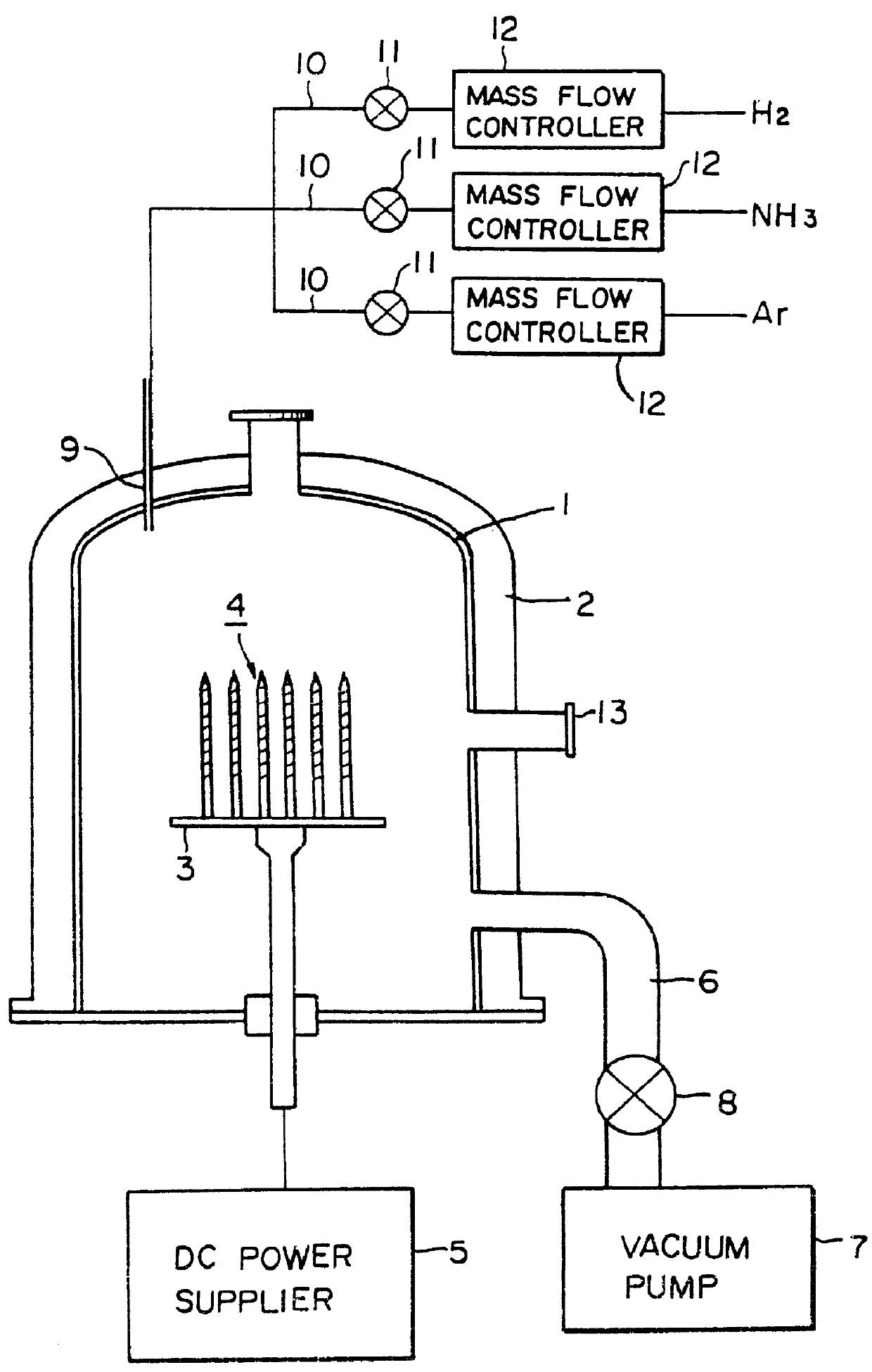
After cleaning a drills (.o slashed.6 mm) of SKH51 high speed steel (Vickers hardness: Hv=850) with ultrasonic waves in an organic solvent, they were placed in an external heating furnace type plasma nitriding apparatus and subjected to plasma nitriding. The inside of the vacuum chamber 1 was evacuated to 1.times.10.sup.-3 Torr by the vacuum pump 7, a hydrogen gas was supplied at 1000 ml / min while continuing evacuation, to maintain the pressure at 1 Torr and, at the same time, the drills were heated by the heating heater 2 till the surface was heated uniformly to 500.degree. C. Then, a voltage at -400 V was applied from the DC power supplier to cause DC glow discharge plasma by the hydrogen gas and the surface of the drills 4 was cleaned for 30 min. Successively, a hydrogen gas and an ammonia gas were introduced each at 2000 ml / min and 500 ml / min, respectively, into the vacuum chamber 1, the pressure was maintained at 1.0 Torr, DC plasma of the hydrogen gas and the ammonia gas were ...

example 4

After conducting plasma nitriding for 30 min in the same procedures as in Example 3 and conducting sputter cleaning in the same manner as in Example 3, a nitrogen gas was at first introduced into the reaction chamber, a bias voltage at -400 V was applied to drills while causing a nitrogen gas to flow such that the pressure in the chamber was kept at 3.times.10.sup.-2 Torr, and arc discharge was generated from the Ti cathode to form a Ti film. The arc discharge was continued for 30 min. Then, application of the voltage to the Ti cathode was interrupted, a bias voltage at -500 V was applied successively to the drills, and arc discharge was generated from the Ti-Al cathode to form a TiAlN film. The arc discharging current was 90 A. The arc discharge was continued for 30 min.

The thickness of the formed nitrided layer (diffusion layer) was 50 .mu.m. The entire thickness of the resultant film was 3 .mu.m and the thickness for each of the layers was 1.5 .mu.m. The surface hardness was Hv 2...


PUM

PropertyMeasurementUnit
temperatureaaaaaaaaaa
current densityaaaaaaaaaa
thicknessaaaaaaaaaa

Abstract

Duplex coated steel composite products comprising a first layer of a nitrided layer formed by applying glow discharge at a current density from 0.001 to 2.0 mA / cm2 to the surface of metal parts by using gaseous ammonia and gaseous hydrogen while maintaining the temperature of the metal parts at 300 to 650 DEG C., thereby applying plasma nitriding and a second layer comprising a hard film comprising a nitride, carbide and / or carbonitride of one or more of elements selected from Ti, Zr, Hf, V, Nb, Ta and Cr coated on the first layer by the PVD method of a laminate film or a gradient laminate film of such hard film. The treated products are excellent in adhesion with the substrate and durability and have both oxidation resistance and wear resistance.

Description

The present invention concerns a technique of plasma nitriding for pretreatment of steel parts to be coated with a hard film, followed by formation of a hard film on the parts by a PVD method and, more in particular, it relates to a duplex coated steel composite product, the hard coating film of which is hardly broken and which is particularly excellent in wear resistance and oxidation resistance, as well as a method of manufacturing such a product.Formation of a hard film by a PVD method is advantageous in that the film can be formed at a relatively low temperature. As the pretreatment for forming a hard film on steel parts to be coated with the hard film, composite treatment generally conducted so far comprises previously subjecting the surface of the parts to plasma nitriding to thereby form a nitrided layer on the surfaces, and then forming a hard film on the nitrided layer whereby adhesion and durability of the thus-formed hard film is improved.According to the existent plasma ...

Claims


Application Information

Patent Timeline
Patent Type & Authority Patents(United States)
IPC IPC(8): C23C8/80C23C8/38C23C14/02C23C8/06C23C14/00C23C14/06
CPCC23C8/38C23C8/80C23C14/0021C23C14/022C23C14/0641C23C14/0664C23C28/044C23C14/024Y10T428/24975Y10T428/265
Inventor YAGINUMA, YOSHIKAZUISHII, YOSHIROOKABE, SHINICHI
Owner SUMITOMO METAL MINING CO LTD
Why Eureka
Try Eureka