Apparatus for processing glass substrate
Inactive Publication Date: 2000-09-19
SONY CORP
5 Cites 86 Cited by
AI-Extracted Technical Summary
Problems solved by technology
However, temperature control at high temperatures according to prior arts cannot be said to be satisfactory.
And, since the process is proceeded with taking the temperature increase of the base material into account, many problems remain to be solved, that is, the process takes a longer time, a throughput is decreased and the reproducibility and controllability of the process decrease due to a large change in temperature.
However, when the mechanical clamp device is used, an in-plane temperature of the glass substrate is non-uniform or it is difficult to suppress the influence of heat transmission from plasma into the base material since the contact between the glass substrate supporting stage and the glass substrate is poor, which consequently causes a problem that the properties and the thickness of the base material formed on the glass substrate fluctuate depending upon positions of the base material on the glass substrate or that the properties of the base material fluctuate in the thickness direction of the base material.
Further, when the base material formed on the glass substrate is etched, there is caused another problem that the form of the etched base material fluctuates depending upon positions of the base material on the glass substrate.
For mounting the electrostatic chuck on the glass substrate supporting stage, how to junction the heated glass substrate supporting stage and a dielectric material constituting the electrostatic chuck is a big problem which remains to be solved.
This problem prevents the practical use of the glass substrate supporting stage on which the electrostatic chuck is mounted.
When the glass substrate supporting stage and the el...
View moreMethod used
, aluminum oxide (Al.sub.2 O.sub.3) is used for a ceramic member to form the matrix 12B. Aluminum oxide has a linear thermal expansion coefficient of 7.8.times.10.sup.-6 /K and a thermal conductivity of 0.069 cal/cm.multidot.second.multidot.K (29 W/m.multidot.K). Further, Aluminum (Al) is used for an aluminum-containing material to form the matrix 12B. The volume ratio of aluminum oxide and aluminum is determined so as to satisfy (.alpha..sub.1 -4).ltoreq..alpha..sub.2 .ltoreq.(.alpha..sub.1 +4), and specifically, the aluminum oxide/aluminum volume ratio is 80/20. The matrix 12B has a linear thermal expansion coefficient of 11.times.10.sup.-6 /K as an average between 100.degree. C. and 300.degree. C. That is, .alpha..sub.1 =11. The material for forming the ceramic layer 13B is Al.sub.2 O.sub.3 containing approximately 1.5% by weight of TiO.sub.2. The ceramic layer 13B is formed on the top and side surfaces of the matrix 12B by a thermal spraying method. The relationship between the linear thermal expansion coefficient .alpha..sub.1 of the matrix 12B and the linear thermal expansion coefficient .alpha..sub.2 of the ceramic layer 13B satisfies (.alpha..sub.1 -4).ltoreq..alpha..sub.2 .ltoreq.(.alpha..sub.1 +4), whereby damage such as cracking of the ceramic layer 13B can be effectively prevented even if a temperature change is caused when the matrix 12B is heated at a high temperature. Further, the specific volume resistance of the ceramic layer 13B can be adjusted to an order of 10.sup.11 .OMEGA./.quadrature. by adding TiO.sub.2 to Al.sub.2 O.sub.3, whereby the ceramic layer 13B effectively functions as an electrostatic chuck.
, silicon carbide (SiC) is used for the ceramic member to form the matrix 12B. Silicon carbide has a linear thermal expansion coefficient of 4.times.10.sup.-6 /K and a thermal conductivity of 0.358 cal/cm.multidot.second.multidot.K (150 W/m.multidot.K). Further, Aluminum (Al) is used for the aluminum-containing material to form the matrix 12B. The volume ratio of silicon carbide and aluminum is determined so as to satisfy (.alpha..sub.1 -4).ltoreq..alpha..sub.2 .ltoreq.(.alpha..sub.1 +4), and specifically, the silicon carbide/aluminum volume ratio is 70/30. The matrix 12B has a linear thermal expansion coefficient of 6.2.times.10.sup.-6 /K as an average between 100.degree. C. and 300.degree. C. That is, .alpha..sub.1 =6.2. The material for forming the ceramic layer 13B is Al.sub.2 O.sub.3 containing approximately 1.5% by weight of TiO.sub.2. The ceramic layer 13B is formed on the top and side surfaces of the matrix 12B by a thermal spraying method. Al.sub.2 O.sub.3 itself has a linear thermal expansion coefficient of approximately 8.times.10.sup.-6 /K, while Al.sub.2 O.sub.3 containing TiO.sub.2 has a linear thermal expansion coefficient of approximately 8 to 9.times.10.sup.-6 /K (.alpha..sub.2 is approximately 8 to 9) as an average between 100.degree. C. and 300.degree. C. The relationship between the linear thermal expansion coefficient .alpha..sub.1 of the matrix 12B and the linear thermal expansion coefficient .alpha..sub.2 of the ceramic layer 13B satisfies (.alpha..sub.1 -4).ltoreq..alpha..sub.2 .ltoreq.(.alpha..sub.1 +4), whereby damage such as cracking of the ceramic layer 13B can be effectively prevented even if a temperature change is caused when the matrix 12B is heated at a high temperature. Further, the specific volume resistance of the ceramic layer 13B can be adjusted to an order of 10.sup.11 .OMEGA./.quadrature. by adding TiO.sub.2 to Al.sub.2 O.sub.3, whereby the ceramic layer 13B effectively functions as an electrostatic chuck.
Aluminum nitride has a linear thermal expansion coefficient of 5.1.times.10.sup.-6 /K and a thermal conductivity of 0.235 cal/cm.multidot.second.multidot.K. Further, the aluminum-containing material for forming the matrix is composed of aluminum (Al). The volume ratio of aluminum nitride and aluminum is determined so as to satisfy (.alpha..sub.1 -4).ltoreq..alpha..sub.2 .ltoreq.(.alpha..sub.1 +4), and specifically, the aluminum nitride/aluminum volume ratio is 70/30. The matrix 12A has a linear thermal expansion coefficient of 8.7.times.10.sup.-6 /K as an average between 100.degree. C. and 300.degree. C. That is, .alpha..sub.1 =8.7. The material for forming the ceramic layer 13A is Al.sub.2 O.sub.3 containing approximately 2.5% by weight of TiO.sub.2. The ceramic layer 13A is formed on the surface of the matrix 12A by a thermal spraying method. The ceramic layer 13A has the same structure as that in Example 1. Al.sub.2 O.sub.3 itself has a linear thermal expansion coefficient of approximately 8.times.10.sup.-6 /K, while Al.sub.2 O.sub.3 containing TiO.sub.2 has a linear thermal expansion coefficient of approximately 9.times.10.sup.-6 /K (.alpha..sub.2 is about 9) as an average between 100.degree. C. and 300.degree. C., which value is nearly equivalent to the linear thermal expansion coefficient .alpha..sub.1 of the matrix 12A. In this manner, damage such as cracking of the ceramic layer 13A can be effectively prevented even if a temperature change is caused when the matrix 12A is heated at a high temperature. Further, the specific volume resistance of the ceramic layer 13A can be adjusted to an order of 10.sup.11 .OMEGA./.quadrature. by adding TiO.sub.2 to Al.sub.2 O.sub.3, whereby the ceramic layer 13A works as a dielectric layer and can effectively exhibit a function as an electrostatic chuck.
In the etching treatment, there can be prevented the occurrence of damage such as cracking of the ceramic layers 213 and 113 of the upper opposing electrode 90, the side wall 94 and the ceiling plate 95. In a conventional etching apparatus, for example, a fluorocarbon polymer precursor formed during discharging is deposited on an upper opposing electrode and a chamber side wall, which causes the fluctuation of carbon/fluorine ratio of plasma during etching. Since, however, the upper opposing electrode 90, the side wall 94 and the ceiling plate 95 can be heated to high temperatures and maintained at the high temperatures, the deposition of the precursor on the upper opposing electrode, the chamber side wall and the ceiling plate can be effectively prevented, which results in the prevention of the fluctuation of carbon/fluorine ratio of plasma during etching, and highly accurate stabilized dry etching treatment can be carried out. Further, since almost no fluorocarbon polymer is deposited on the upper opposing electrode, the chamber side wall and the ceiling plate, the particle level is not downgraded even if the etching procedures are repeated many times.
In the glass substrate processing apparatus of the present invention, part thereof, for example, the glass substrate supporting stage, comprises the composite material. Therefore, the occurrence of damage of the ceramic layer caused by thermal expansion of the matrix and the ceramic layer can be prevented, and the composite material can be reliably used at high temperatures. Further, the ceramic layer is formed on the surface of the matrix by a thermal spraying method. Therefore, the composite material having a large area c...
View moreBenefits of technology
It is an object of the present invention to provide a glass substrate processing apparatus which can avoid the occurrence of damage caused by a thermal expansion coefficient difference between materials constituting the glass substrate processin...
View moreAbstract
A glass substrate processing apparatus, part of which comprises a composite material, the composite material being formed of a matrix and a ceramic layer formed on a surface of the matrix by a thermal spraying method, the matrix being formed of a ceramic member and an aluminum-containing material filled in a texture of the ceramic member.
Application Domain
Technology Topic
Thermal sprayingMetallurgy
Image
Examples
- Experimental program(6)
Example
With a glass substrate processing apparatus in Example 1, a base material formed on a glass substrate is etched. Part of the glass substrate processing apparatus comprises a composite material 11, and it is a glass substrate supporting stage having an electrostatic chuck function and having temperature control means. An electrode 14 is formed within a ceramic layer 13, and the ceramic layer 13 has the electrostatic chuck function. FIG. 1A shows a schematic cross-sectional view of the glass substrate supporting stage 10 comprising the composite material 11, and FIG. 1B shows an enlarged cross-sectional view of the top surface end portion of the composite material 11. The glass substrate supporting stage 10 comprises the composite material 11. The composite material 11 is formed of a matrix 12 (corresponding to a temperature adjusting jacket) and the ceramic layer 13. The matrix 12 is formed of a ceramic member and an aluminum-containing material filled in a texture of the ceramic member. The ceramic layer 13 is formed on a surface of the matrix 12 by a thermal spraying method. The matrix 12 has the form of a disc.
In Example 1, the ceramic member for forming the matrix 12 is composed of cordierite ceramic. The cordierite ceramic is ceramic prepared so as to have a composition having an MgO content of about 13% by weight, an SiO.sub.2 content of about 52% by weight and an Al.sub.2 O.sub.3 content of about 35% by weight. The cordierite ceramic has a linear thermal expansion coefficient of 0.1.times.10.sup.-6 /K.
The aluminum-containing material for forming the matrix 12 has a composition containing aluminum (Al) and silicon (Si). In Example 1, the aluminum-containing material contains 20% by volume, based of the aluminum-containing material, of silicon. The ceramic member is a sintered member of a mixture of a cordierite ceramic powder and a cordierite ceramic fiber, and the sintered member has a cordierite ceramic fiber content of 5% by volume. The cordierite ceramic powder has an average particle diameter of 10 .mu.m, and the cordierite ceramic fiber has an average diameter of 3 .mu.m and an average length of 1 mm. The ceramic member has a porosity of approximately 50%, and pores have a diameter of approximately 1 to 2 .mu.m. Therefore, the cordierite ceramic/aluminum-containing material volume ratio is approximately 1/1. The matrix 12 having the above constitution has a linear thermal expansion coefficient of approximately 10.6.times.10.sup.-6 /K as an average value between 100.degree. C. and 300.degree. C. That is, .alpha..sub.1 =10.6. Since the cordierite ceramic/aluminum-containing material volume ratio is approximately 1/1, the matrix 12 has an electric conductivity value and a thermal conductivity value which are closer to those of a metal than to those of a pure ceramic.
Al.sub.2 O.sub.3 containing approximately 2.5% by weight of TiO.sub.2 is used as a material for forming the ceramic layer 13. An electrode 14 is formed within the ceramic layer 13. The ceramic layer 13 is formed on the surface of the matrix 12 by a thermal spraying method. The ceramic layer 13 having the above composition has a linear thermal expansion coefficient of approximately 9.times.10.sup.-6 /K as an average value between 100.degree. C. and 300.degree. C. Therefore, .alpha..sub.2 is 9, and the linear thermal expansion coefficient .alpha..sub.1 satisfies the relationship of (.alpha..sub.1 -4).ltoreq..alpha..sub.2 .ltoreq.(.alpha..sub.1 +4). Al.sub.2 O.sub.3 itself has a linear thermal expansion coefficient of approximately 8.times.10.sup.-6 /K. Further, the specific volume resistance of the ceramic layer 13 can be adjusted to an order of 10.sup.11 .OMEGA./.quadrature. by adding about 2.5% by weight of TiO.sub.2 to Al.sub.2 O.sub.3, whereby the ceramic layer 13 works as a dielectric layer and can exhibit a function as an electrostatic chuck owing to the electrode 14 formed within it. The reason for the above adjustment of the specific volume resistance value is that when the ceramic layer 13 has a specific volume resistance exceeding an order of 10.sup.11 .OMEGA./.quadrature., the attracting force of the ceramic layer 13 is too low when the ceramic layer 13 is used as an electrostatic chuck, and it may be difficult to allow a glass substrate to be fully attracted to the ceramic layer 13. When the specific volume resistance of the ceramic layer 13 is lower than an order of 10.sup.11 .OMEGA./.quadrature., the resistance value of the ceramic layer 13 further decreases when the glass substrate supporting stage 10 is used at a high temperature, and electric current may flow in an interface between a glass substrate and the ceramic layer 13. Although differing depending upon use conditions, generally, the specific volume resistance value of the ceramic layer is preferably 10.sup.11 to 10.sup.16 .OMEGA./.quadrature..
The temperature control means is provided (embedded) in the matrix 12 of the glass substrate supporting stage 10. The temperature control means comprises a heater 15 and a piping 16 for flowing a temperature-control heating medium therein.
As the heater 15, there is used a large-sized large-capacity sheathed heater matching the area (bottom area) of the matrix 12. The heater 15 is a known heater, and comprises a heater element (not shown) and a sheath (not shown) disposed outside the heater element for protecting the heater element. The heater 15 is connected to a power source through a wiring (not shown). The thermal expansion of the heater 15 influences the glass substrate supporting stage 10. Preferably, the heater 15 is therefore formed of a material having a linear thermal expansion coefficient value close to the linear thermal expansion coefficients .alpha..sub.1 and .alpha..sub.2 of the matrix 12 and the ceramic layer 13. Specifically, it is preferred to use a sheath composed of a material having a linear thermal expansion coefficient of 9.times.10.sup.-6 /K to 12.times.10.sup.-6 /K, such as titanium or stainless steel. That is, preferably, the linear thermal expansion coefficient .alpha..sub.1 [unit: 10.sup.-6 /K] of the material constituting the heater 15 (the material for the sheath contacting the matrix 12) satisfies (.alpha..sub.1 -4).ltoreq..alpha..sub.H .ltoreq.(.alpha..sub.1 +4). Since a linear thermal expansion coefficient of the heater element has no influence on the glass substrate supporting stage 10, the material constituting the heater element is not critical.
The piping 16 is connected to a temperature-controlling heating medium supply device (not shown in FIG. 1A) and is made of a metal or an alloy. A temperature-controlling heating medium supplied from the temperature-controlling heating medium supply device is flowed through the piping 16 within the glass substrate supporting stage 10, whereby the temperature of the glass substrate supporting stage 10 can be controlled. The thermal expansion of the piping 16 influences the glass substrate supporting stage 10. Preferably, the piping 16 is therefore composed of a material having a linear thermal expansion coefficient value close to the linear thermal expansion coefficients .alpha..sub.1 and .alpha..sub.2 of the matrix 12 and the ceramic layer 13. Specifically, it is preferred to use a piping composed of a material having a linear thermal expansion coefficient of 9.times.10.sup.-6 /K to 12.times.10.sup.-6 /K, such as titanium or stainless steel. That is, preferably, the linear thermal expansion coefficient .alpha..sub.P [unit: 10.sup.-6 /K] of the material constituting the piping 16 satisfies (.alpha..sub.1 -4).ltoreq..alpha..sub.P >(.alpha..sub.1 +4).
When a direct current is applied to the electrode 14 of the glass substrate supporting stage 10 having the above constitution through a wiring (not shown), the ceramic layer 13 works as an electrostatic chuck. Pusher pins (not shown) are embedded in the glass substrate supporting stage 10, which pusher pins are for pushing up a glass substrate placed and supported on the ceramic layer 13. The pusher pins are provided with a mechanism (not shown) for pushing the pusher pins up above or down from the top surface of the ceramic layer 13.
The method of producing the glass substrate supporting stage 10 comprising the composite material 11 will be explained below. The composite material 11 is produced by a step (A) of filling the aluminum-containing material in the texture of the ceramic member to manufacture the matrix in which the aluminum-containing material is filled in the texture of the ceramic member, and a step (B) of forming the ceramic layer on the surface of the matrix by a thermal spraying method. In Example 1, the step (A) comprises the steps of placing the ceramic member composed of porous cordierite ceramic in a container (mold), and casting the aluminum-containing material composed of aluminum and silicon into the container (mold) to fill the aluminum-containing material in the texture of the ceramic member by a high-pressure casting method.
The ceramic member composed of porous cordierite ceramic is formed as a porous member in a sintering step on the preparation of the ceramic member. As porous cordierite ceramic member, Example 1 uses a porous cordierite ceramic-fiber board (to be abbreviated as "fiber board" hereinafter) which is a sintered member obtained by sintering a mixture of a cordierite ceramic powder and a cordierite ceramic fiber. A general powder-sintered ceramic member is obtained by sintering at a high temperature of 1200.degree. C., while the fiber board is obtained by sintering at a low temperature of approximately 800.degree. C. and is formed into a porous member by sintering so as to have cordierite ceramic powder bonding intimately to surfaces of cordierite ceramic fibers with binders. Therefore, the porosity and the pore diameter of the ceramic member composed of porous cordierite ceramic to be obtained can be adjusted by changing the volume ratio of the cordierite ceramic powder and the cordierite ceramic fiber.
For producing the glass substrate supporting stage 10, first, a first fiber board shaped in the form of a predetermined disc is provided. A groove is made in the first fiber board for disposing the heater 15 therein. Separately, a second fiber board is provided. A groove is made in the second fiber board for disposing the piping 16 therein. Then, the first fiber board is placed on the bottom of the container (mold), and then heater 15 is arranged in the groove made in the first fiber board. The second fiber board is placed on the first fiber board, and the piping 16 is arranged in the groove made in the second fiber board. Further, a third fiber board is placed on the second fiber board. These fiber boards have holes made beforehand for embedding the pusher pins therein.
Then, the ceramic member comprising the above fiber boards is preliminarily heated up to approximately 800.degree. C., and thereafter, the aluminum-containing material (80% by volume of Al--20% by volume of Si) which is brought into a molten state by heating is cast therein. Then, a high-pressure casting method is carried out for applying a high pressure of approximately 1 metric ton/cm.sup.2 into the container (mold). As a result, the aluminum-containing material is filled in the porous fiber boards, i.e., the texture of the ceramic member. The aluminum-containing material is cooled to solidness to give the matrix 12.
Then, the top surface of the matrix 12 is polished. Thereafter, a powder mixture having a particle diameter of about 10 .mu.m, prepared by mixing Al.sub.2 O.sub.3 with about 2.5% by weight of TiO.sub.2, is sprayed in a fused state onto the polished surface by a vacuum thermal spraying method and solidified, whereby a first ceramic layer 130A having a specific volume resistance value of an order of 10.sup.11 .OMEGA./.quadrature. can be formed by a thermal spraying method. Before the formation of the first ceramic layer 130A, nickel containing approximately 5% by weight of aluminum (Ni-5 wt % Al) may be thermal-sprayed to form a thermal-spray undercoat layer, and the first ceramic layer 130A may be formed on the thermal-spray undercoat layer by a thermal spraying method. Then, a brazing material is used to form the electrode 14 on the first ceramic layer 130A. FIG. 1C schematically shows a plan configuration of the electrode 14. The electrode 14 has the form of a so-called comb-shaped electrode and has a bipolar system. In FIG. 1C, the electrode 14 is indicated by slanting lines for clearly showing the electrode 14. Although not specially limited, the brazing material can be selected from Al--Mg--Ge alloy, titanium alloy, tin alloy, antimony alloy or magnesium alloy. When the matrix has a linear thermal expansion coefficient .alpha..sub.1 [unit: 10.sup.-6 /K], preferably, a linear thermal expansion coefficient [unit: 10.sup.-6 /K] of the brazing material is also in the range of from (.alpha..sub.1 -4) to (.alpha..sub.1 +4). When the electrode 14 has a small thickness, almost no problem takes place even if the linear thermal expansion coefficient of the brazing material is outside the above range. Then, a second ceramic layer 130B is formed by spraying a powder mixture having a particle diameter of approximately 10 .mu.m, which mixture is prepared by mixing Al.sub.2 O.sub.3 with about 2.5% by weight of TiO.sub.2, onto the entire surface by a thermal spraying method while the powder mixture is in a fused state, and solidifying the sprayed powder mixture. In this manner, there can be formed the ceramic layer 13 (first ceramic layer 130A and second ceramic layer 130B) having the electrode 14 formed inside. In Figures other than FIG. 1B, the ceramic layer is shown as one layer.
For studying the breaking prevention of the above-produced ceramic layer 13 of the glass substrate supporting stage 10, the glass substrate supporting stage 10 was subjected to a heat cycle test using a hot air circulation type oven.
(1) The glass substrate supporting stage 10 was placed in the oven and the temperature in the oven was increased up to 300.degree. C. over 30 minutes.
(2) The temperature in the oven was maintained at 300.degree. C. for 20 minutes.
(3) The temperature in the oven was decreased to room temperature over 40 minutes.
(4) The glass substrate supporting stage 10 was taken out of the oven, and its appearance was observed.
The above procedures of (1) to (4) were repeated 10 times to show that no change was found on the appearance of the glass substrate supporting stage 10. It was found that the ceramic layer 13 had no damage such as cracking.
The above-obtained glass substrate supporting stage 10 comprises the matrix (temperature adjusting jacket) 12 which is obtained by filling the aluminum-containing material formed of 80% by volume of Al and 20% by volume of Si in the texture of the ceramic member composed of the porous cordierite ceramic fiber boards, and the linear thermal expansion coefficient .alpha..sub.1 of the matrix 12 is close to the linear thermal expansion coefficient .alpha..sub.2 of the ceramic layer 13. Therefore, when the glass substrate supporting stage 10 is heated or cooled, the expansion and shrinkage degrees of the matrix 12 and those of the ceramic layer 13 are almost equal. There can be therefore reliably prevented the occurrence of damage such as cracking of the ceramic layer 13, which damage is to be caused, due to a difference between the linear thermal expansion coefficients .alpha..sub.1 and .alpha..sub.2 of the matrix 12 and the ceramic layer 13, during heating at high temperatures or when the glass substrate supporting stage 10 is brought into room temperature from high temperatures.
The production of the composite material in Example 1 uses the cordierite ceramic fiber boards in particular, and the fiber boards has sufficient resistance against an impact caused when the aluminum-containing material infiltrates the pores thereof during the production by a high-pressure casting method. As a result, the cracking of the fiber boards can be prevented. That is, a ceramic member composed of porous cordierite ceramic obtained by a general powder sintering method is liable to undergo cracking during a high-pressure casting. However, the cracking of the ceramic member during the high-pressure casting can be prevented by using the porous cordierite ceramic fiber board(s).
Since the occurrence of cracking, etc., of the fiber board during the high-pressure casting can be avoided, the occurrence of cracking, etc., of the ceramic layer 13 formed on the surface of the matrix 12 can be more reliably prevented. That is, even if a ceramic member undergoes cracking, an aluminum-containing material filled in a texture of the ceramic member works as a binder, and as a result, a matrix can be obtained. In the so-obtained matrix, however, layers of aluminum-containing material are formed in gaps such as cracks in the so-obtained matrix. As a result, a ceramic layer formed on the matrix can no longer follow temperature changes when the glass substrate supporting stage is used, and the ceramic layer is liable to undergo cracking. That is, the ceramic layer is formed by thermal spraying a powder mixture having a particle diameter of approximately 10 .mu.m to be integrated onto the matrix, and it is therefore almost free from an influence of thermal expansion of the aluminum-containing material filled in the pores having a diameter of 1 to 2 .mu.m in the ceramic member. However, the layers formed of aluminum-containing material, which are present in cracks in the ceramic member, have a length and a width greater than those of particles forming the ceramic layer. Therefore, the influence of thermal expansion of these layers formed of aluminum-containing material on the ceramic layer is no longer negligible, and the possibility of the ceramic layer being cracked increases.
Since the ceramic layer 13 is formed on the matrix 12 by a thermal spraying method, the composite material 11 having large dimensions can be easily produced. Further, since the matrix 12 and the ceramic layer 13 are integrated to a far higher degree, not only can a stress between the matrix 12 and the ceramic layer 13 be eased, but also the heat conduction from the matrix 12 to the ceramic layer 13 is promoted, so that the temperature control of a glass substrate held and supported on the ceramic layer 13 can be more smoothly and reliably carried out.
FIG. 2 shows a conceptual view of a dry etching apparatus 20 (to be abbreviated as "etching apparatus" hereinafter) which is a glass substrate processing apparatus according to the present invention and having the above glass substrate supporting stage 10 incorporated. The etching apparatus 20 further has a chamber 21, RF antennas 22, an RF antenna 23 and a multi-pole magnet 24.
The two RF antennas 22 are disposed by turning them around a belljar 25 constituting an upper portion of the chamber 21 and one made of cylindrical quartz, and they have an antenna form for generating M=1 mode plasma and are connected to a helicon wave plasma generation source 28 through a matching network 27. Outside these RF antennas 22 is disposed a solenoid coil assembly 26 comprising an inner coil and an outer coil. Of the solenoid coil assembly 26, the inner coil serves to propagate helicon wave, and the outer coil serves to transport the generated plasma. The RF antenna 23 having a form of loop is disposed above a ceiling plate 25A of the chamber 21, and it is connected to a power source 30 through a matching network 29. The ceiling plate 25A is made of quartz. The multi-pole magnet 24 is disposed outside a lower portion of the chamber 21 and forms a cusped magnetic field for preventing the decay of electron on a side wall of the chamber 21.
Inside the chamber 21 is disposed the glass substrate supporting stage 10 (see FIG. 1A) for holding and supporting a glass substrate 40. Further, a discharge outlet 31 for discharging gas in the chamber 21 is connected to negative pressure means (not shown) such as a vacuum pump. A bias power source 32 for controlling incident ion energy on a base material (not shown in FIG. 2) formed on the glass substrate 40 is connected to the glass substrate supporting stage 10. Further, for allowing the ceramic layer 13 to exhibit an electrostatic attracting force, a DC power source 33 is connected to the electrode 14 formed within the ceramic layer 13. The heater 15 disposed within the matrix 12 of the glass substrate supporting stage 10 is connected to a power source 39. Further, the etching apparatus 20 is provided with a fluorescence fiber thermometer 36 for measuring the glass substrate 40 for temperatures.
The piping 16 arranged within the matrix 12 of the glass substrate supporting stage 10 is connected to a temperature-controlling heating medium supply device 35 through pipings 34A and 34B. The temperature-controlling heating medium supply device 35 supplies a temperature-controlling heating medium such as silicone oil to the piping 16 in the glass substrate supporting stage 10 through the piping 34A, receives the temperature-controlling heating medium sent out with the piping 16 through the piping 34B and heats or cools the temperature-controlling heating medium to a predetermined temperature. In some cases, a chiller may be incorporated into the temperature-controlling heating medium supply device 35 to flow a low-temperature temperature-controlling heating medium such as chlorofluorocarbon gas (hydrofluorocarbon gas) in the pipings 34A, 16 and 34B. The glass substrate 40 held and supported on the glass substrate supporting stage 10 is temperature-controlled by circulating the temperature-controlling heating medium in the piping 16 as described above. The piping 34A connected to the temperature-controlling heating medium supply device 35 is provided with a control valve 37 operable at high temperature. Further, a bypass piping 34C located between the pipings 34A and 34B is also provided with a control valve 37. In the above constitution, the supply amount of the temperature-controlling heating medium to the piping 16 is controlled by controlling the open-close degree of the control valves 37. Further, a temperature sensed with the fluorescence fiber thermometer 36 is detected with a control unit (PID controller) 38, and the control unit 38 determines a supply amount of the temperature-controlling heating medium on the basis of a difference of the detected temperature from a predetermined temperature of the glass substrate 40 so as to supply temperature-controlling heating medium in an amount predetermined by experiments and calculations.
In the glass substrate supporting stage 10 shown in FIG. 1A, generally, temperatures are controlled mainly by heating with the heater 15 although temperature control is not always so depending upon the predetermined temperature of the glass substrate 40. The temperature control of the glass substrate supporting stage 10 with the temperature-controlling heating medium is an auxiliary temperature control for stabilizing the temperature of the glass substrate 40. That is, in plasma etching, etc., not only a base material but also the glass substrate 40 receives heat from plasma, and as a result, it is sometimes difficult to maintain the glass substrate 40 at a predetermined temperature by heating with the heater 15 alone. In this case, in addition to heating with the heater 15, the temperature-controlling heating medium having a lower temperature than a predetermined temperature is flowed in the piping 16 so as to offset heat from plasma, for maintaining the glass substrate 40 at the predetermined temperature. In this manner, the glass substrate 40 can be stabilized at the predetermined temperature. In FIG. 2, showing of particulars of etching apparatus such as an etching gas inlet port, a gate valve, etc., is omitted.
When a base material formed on the glass substrate 40 is plasma-etched by means of the etching apparatus 20 shown in FIG. 2, the glass substrate 40 shows almost no temperature increase caused by heat from plasma during etching treatment, and the glass substrate 40 can be stably maintained at a predetermined temperature. Since the temperature (for example, 250.degree. C.) of the glass substrate 40 can be stabilized highly accurately, an excellent anisotropic configuration can be formed in the base material. That is, since the glass substrate supporting stage 10 is allowed to exhibit electrostatic attracting force, the base material can be temperature-controlled with high accuracy which cannot be accomplished by any conventional technique.
Example
Example 2 is a variant of Example 1. Example 2 differs from Example 1 in that the ceramic member for forming the matrix of the composite material is replaced with aluminum nitride and that the aluminum-containing material for forming the matrix is replaced with aluminum.
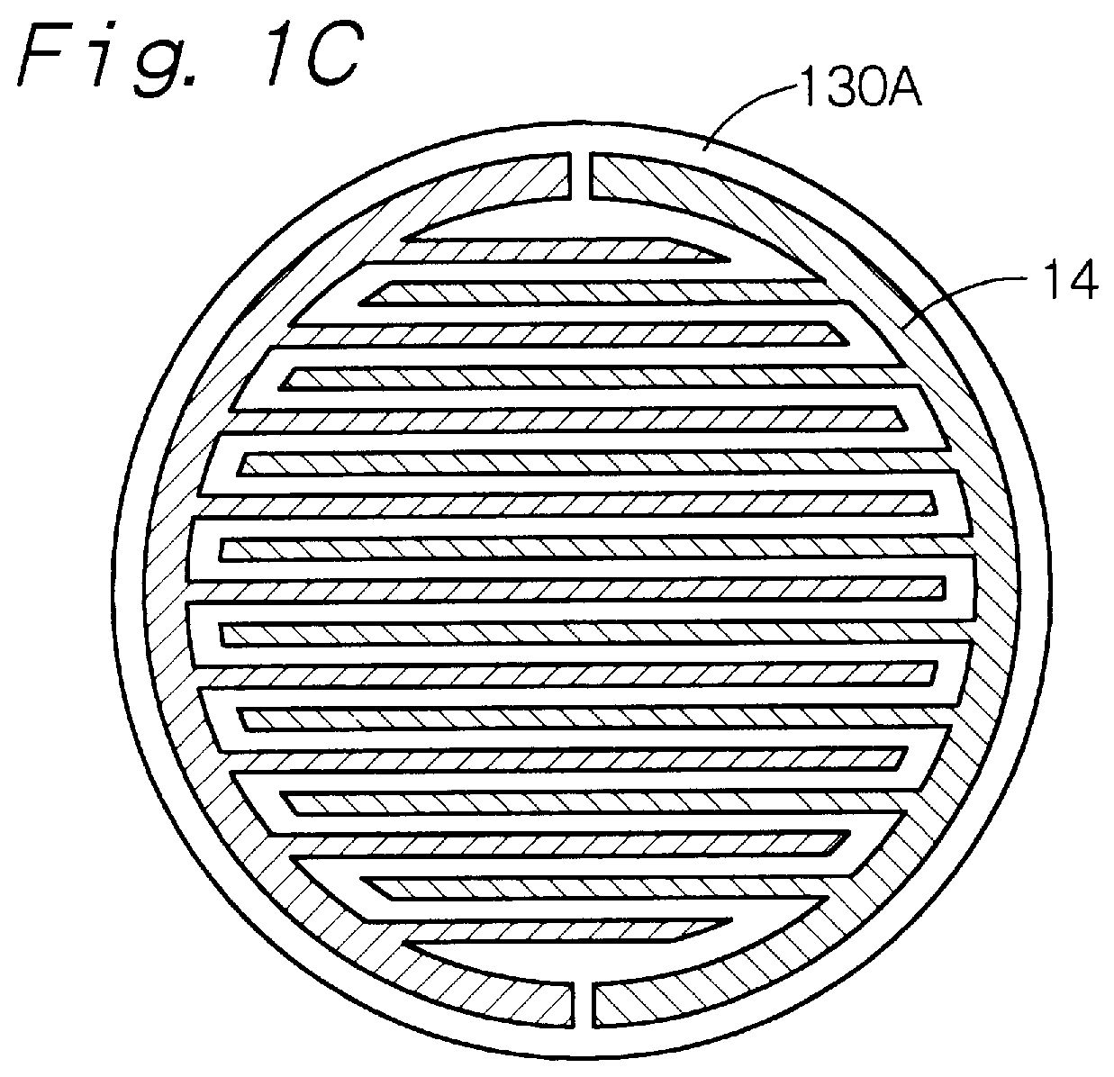
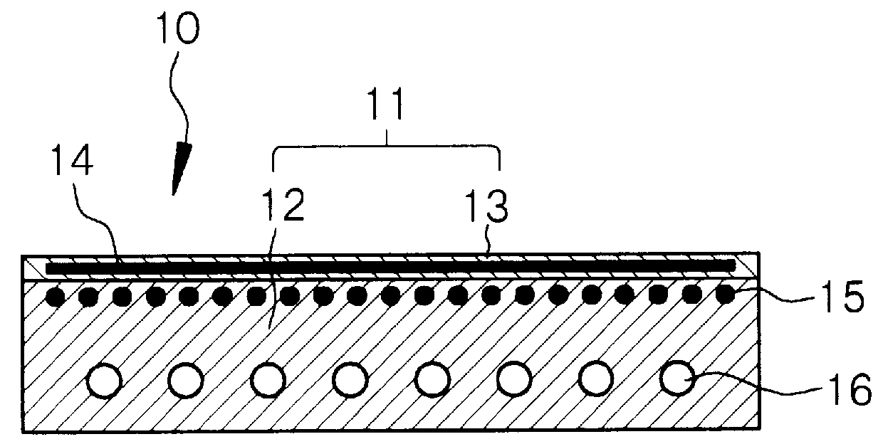
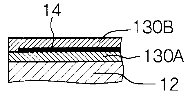
FIG. 3A shows a schematic cross-sectional view of a glass substrate supporting stage 10A in Example 2 which is part of a glass substrate processing apparatus. The glass substrate supporting stage 10A comprises a composite material 11A. The composite material 11A is formed of a matrix 12A (corresponding to a temperature adjusting jacket) in which the aluminum-containing material is filled in a texture of a ceramic member and a ceramic layer 13A formed on the surface of the matrix 12A by a thermal spraying method. An electrode 14A is formed within the ceramic layer 13A. The matrix 12A has the form of a disc. Unlike Example 1, a heater 15A is attached to a bottom surface of the matrix 12A.
In Example 2, the ceramic member for forming the matrix 12A is composed of aluminum nitride (AlN).
Aluminum nitride has a linear thermal expansion coefficient of 5.1.times.10.sup.-6 /K and a thermal conductivity of 0.235 cal/cm.multidot.second.multidot.K. Further, the aluminum-containing material for forming the matrix is composed of aluminum (Al). The volume ratio of aluminum nitride and aluminum is determined so as to satisfy (.alpha..sub.1 -4).ltoreq..alpha..sub.2 .ltoreq.(.alpha..sub.1 +4), and specifically, the aluminum nitride/aluminum volume ratio is 70/30. The matrix 12A has a linear thermal expansion coefficient of 8.7.times.10.sup.-6 /K as an average between 100.degree. C. and 300.degree. C. That is, .alpha..sub.1 =8.7. The material for forming the ceramic layer 13A is Al.sub.2 O.sub.3 containing approximately 2.5% by weight of TiO.sub.2. The ceramic layer 13A is formed on the surface of the matrix 12A by a thermal spraying method. The ceramic layer 13A has the same structure as that in Example 1. Al.sub.2 O.sub.3 itself has a linear thermal expansion coefficient of approximately 8.times.10.sup.-6 /K, while Al.sub.2 O.sub.3 containing TiO.sub.2 has a linear thermal expansion coefficient of approximately 9.times.10.sup.-6 /K (.alpha..sub.2 is about 9) as an average between 100.degree. C. and 300.degree. C., which value is nearly equivalent to the linear thermal expansion coefficient .alpha..sub.1 of the matrix 12A. In this manner, damage such as cracking of the ceramic layer 13A can be effectively prevented even if a temperature change is caused when the matrix 12A is heated at a high temperature. Further, the specific volume resistance of the ceramic layer 13A can be adjusted to an order of 10.sup.11 .OMEGA./.quadrature. by adding TiO.sub.2 to Al.sub.2 O.sub.3, whereby the ceramic layer 13A works as a dielectric layer and can effectively exhibit a function as an electrostatic chuck.
A heater 15A is a PBN heater (pyrolytic boron nitride-pyrolytic graphite heater) which can heat up to approximately 400.degree. C. The heater 15A is attached to a bottom surface of the matrix 12A, whereby the matrix 12A can be temperature-controlled in a range of from room temperature to approximately 400.degree. C. When DC current is applied to the electrode 14A of the glass substrate supporting stage 10A through a wiring (not shown), the ceramic layer 13A works as an electrostatic chuck. Pusher pins (not shown) are embedded in the glass substrate supporting stage 10A, which pusher pins are for pushing up a glass substrate placed and supported on the ceramic layer 13A. Further, the pusher pins are provided with a mechanism (not shown) for pushing the pusher pins up above or down from the top surface of the ceramic layer 13A.
The method of producing the glass substrate supporting stage 10A will be explained below. Like Example 1, the composite material 11A is produced by a step (A) of filling an aluminum-containing material in a texture of a ceramic member to manufacture a matrix in which an aluminum-containing material is filled in the texture of the ceramic member and a step (B) of forming a ceramic layer on the surface of the matrix by a thermal spraying method. In Example 2, the step (A) comprises the step of infiltrating the aluminum-containing material composed of molten aluminum into the ceramic member composed of aluminum nitride particles in a non-pressurized state by a non-pressurized metal infiltration method.
Specifically, AlN particles having an average particle diameter of 10 .mu.m are preformed by a slurry pouring method, and then the AlN particles are sintered at a temperature of approximately 800.degree. C., to give the ceramic member which is a preform obtained by shaping the AlN particles. And, the ceramic member is preheated to approximately 800.degree. C., and aluminum which is melted by heating it to approximately 800.degree. C. is infiltrated into the texture of the ceramic member in a non-pressurized state, whereby the matrix 12A formed of 70% by volume of AlN and 30% by volume of Al can be produced. Then, the matrix 12A is processed into the form of a disc-shaped temperature adjusting jacket. The matrix 12A has holes made for embedding the pusher pins, etc., therein. Then, the top surface of the so-obtained matrix 12A is polished.
Then, a powder mixture which is prepared by mixing Al.sub.2 O.sub.3 with approximately 2.5% by weight of TiO.sub.2 and has a particle diameter of approximately 10 .mu.m is sprayed onto the polished surface in a fused state by a vacuum thermal spraying method and is solidified, whereby a first ceramic layer having a specific volume resistance value of an order of 10.sup.11 .OMEGA./.quadrature. can be formed by a thermal spraying method. Before the formation of the first ceramic layer, for example, nickel containing approximately 5% by weight of aluminum (Ni-5 wt % Al) may be thermal-sprayed to form a thermal-spray undercoat layer, and the first ceramic layer may be formed on the thermal-spray undercoat layer by a thermal spraying method. Then, the electrode 14 is formed on the first ceramic layer by a thermal spraying method. The electrode 14 has a bipolar system. Then, a powder mixture which is prepared by mixing Al.sub.2 O.sub.3 with approximately 2.5% by weight of TiO.sub.2 and has a particle diameter of approximately 10 .mu.m is sprayed onto the entire surface in a fused state by a vacuum thermal spraying method and then solidified, whereby a second ceramic layer is formed by a thermal spraying method. In this manner, the ceramic layer 13 (first ceramic layer and second ceramic layer) having the electrode 14 formed inside can be formed. Then, the heater 15A which is a PBN heater is attached to the bottom surface of the matrix 12A, i.e., a surface opposite to the surface on which the ceramic layer 13A is formed, to give the glass substrate supporting stage 10A.
In the so-produced glass substrate supporting stage 10A, a linear thermal expansion coefficient .alpha..sub.2 of the ceramic layer 13A is nearly equivalent to a linear thermal expansion coefficient .alpha..sub.1 of the matrix 12A.
Therefore, even if a temperature change is caused by heating the matrix 12A at a high temperature, the ceramic layer 13A is free from damage such as cracking.
In Example 2, the linear thermal expansion coefficient .alpha..sub.1 of the matrix 12A and the linear thermal expansion coefficient .alpha..sub.2 of the ceramic layer 13A can be adjusted to satisfy (.alpha..sub.1 -4).ltoreq..alpha..sub.2 .ltoreq.(.alpha..sub.1 +4) by adjusting the volume ratio of aluminum nitride and aluminum and optionally by adjusting the content of TiO.sub.2 in the ceramic layer 13A composed of Al.sub.2 O.sub.3 as required. As a result, damage such as cracking of the ceramic layer 13A caused by a temperature change of the glass substrate supporting stage 10A can be effectively prevented.
Since the ceramic layer 13A is formed on the matrix 12A by a thermal spraying method, a composite material having a large area can be easily produced, and the processing of a glass substrate having a large area can be easily accomplished. Further, since the matrix 12A and the ceramic layer 13A are integrated to a far higher degree, not only a stress between the matrix 12A and the ceramic layer 13A can be eased, but also the heat conduction from the matrix 12A to the ceramic layer 13A is promoted, so that the temperature control of a glass substrate held and supported on the ceramic layer 13A can be more smoothly and reliably carried out.
The etching apparatus 20A in Example 2, which is a glass substrate processing apparatus having, as part thereof, the above glass substrate supporting stage 10A composed of the composite material 11A, can be substantially the same as the glass substrate processing apparatus explained in Example 1 except for a piping 16 and accessories thereto, as is shown in a conceptual view of FIG. 4. Therefore, detailed explanations thereof are omitted. The temperature of the glass substrate supporting stage 10A can be controlled by detecting a temperature sensed with a fluorescence fiber thermometer 36 with a control device (PID controller) 38 and controlling a power source 39 which is for supplying power to the heater 15A.
The aluminum used for the aluminum-containing material to form the matrix may be replaced with aluminum and silicon. When the aluminum-containing material is composed of aluminum and silicon (for example, 80% by volume of Al and 20% by volume of Si), the linear thermal expansion coefficient .alpha..sub.1 of the matrix can be controlled, and the difference of the linear thermal expansion coefficient .alpha..sub.1 of the matrix from the linear thermal expansion coefficient .alpha..sub.2 of the ceramic layer can be further decreased. Further, Al.sub.2 O.sub.3 for forming the ceramic layer may be replaced with aluminum nitride (AlN).
Example
Example 3 is also a variant of Example 1. Example 3 differs from Example 1 in that silicon carbide (SiC) is used for a ceramic member to form the matrix of the composite material and that aluminum (Al) is used for an aluminum-containing material to form the matrix.
FIG. 3B shows a schematic cross-sectional view of a glass substrate supporting stage 10B in Example 3 which is part of a glass substrate processing apparatus. The glass substrate supporting stage 10B comprises a composite material 11B. The composite material 11B is formed of a matrix 12B (corresponding to a temperature adjusting jacket) in which an aluminum-containing material is filled in a texture of a ceramic member and a ceramic layer 13B formed on top and side surfaces of the matrix 12B by a thermal spraying method. The matrix 12B has the form of a disc. Like Example 2, a heater 15B is attached to a bottom surface of the matrix 12B. Further, the ceramic layer 13B has an electrode 14B formed inside.
In Example 3, silicon carbide (SiC) is used for the ceramic member to form the matrix 12B. Silicon carbide has a linear thermal expansion coefficient of 4.times.10.sup.-6 /K and a thermal conductivity of 0.358 cal/cm.multidot.second.multidot.K (150 W/m.multidot.K). Further, Aluminum (Al) is used for the aluminum-containing material to form the matrix 12B. The volume ratio of silicon carbide and aluminum is determined so as to satisfy (.alpha..sub.1 -4).ltoreq..alpha..sub.2 .ltoreq.(.alpha..sub.1 +4), and specifically, the silicon carbide/aluminum volume ratio is 70/30. The matrix 12B has a linear thermal expansion coefficient of 6.2.times.10.sup.-6 /K as an average between 100.degree. C. and 300.degree. C. That is, .alpha..sub.1 =6.2. The material for forming the ceramic layer 13B is Al.sub.2 O.sub.3 containing approximately 1.5% by weight of TiO.sub.2. The ceramic layer 13B is formed on the top and side surfaces of the matrix 12B by a thermal spraying method. Al.sub.2 O.sub.3 itself has a linear thermal expansion coefficient of approximately 8.times.10.sup.-6 /K, while Al.sub.2 O.sub.3 containing TiO.sub.2 has a linear thermal expansion coefficient of approximately 8 to 9.times.10.sup.-6 /K (.alpha..sub.2 is approximately 8 to 9) as an average between 100.degree. C. and 300.degree. C. The relationship between the linear thermal expansion coefficient .alpha..sub.1 of the matrix 12B and the linear thermal expansion coefficient .alpha..sub.2 of the ceramic layer 13B satisfies (.alpha..sub.1 -4).ltoreq..alpha..sub.2 .ltoreq.(.alpha..sub.1 +4), whereby damage such as cracking of the ceramic layer 13B can be effectively prevented even if a temperature change is caused when the matrix 12B is heated at a high temperature. Further, the specific volume resistance of the ceramic layer 13B can be adjusted to an order of 10.sup.11 .OMEGA./.quadrature. by adding TiO.sub.2 to Al.sub.2 O.sub.3, whereby the ceramic layer 13B effectively functions as an electrostatic chuck.
The heater 15B is a PBN heater like Example 2. The heater 15B is attached to the bottom surface of the temperature adjusting jacket which is the matrix 12B, whereby the matrix 12B can be temperature-controlled in a range of from room temperature to approximately 400.degree. C. When DC current is applied to the electrode 14B through a wiring (not shown), the ceramic layer 13B works as an electrostatic chuck. Pusher pins (not shown) are embedded in the glass substrate supporting stage 10B, which pusher pins are for pushing up a glass substrate placed and supported on the ceramic layer 13B. Further, the pusher pins are provided with a mechanism (not shown) for pushing the pusher pins up above or down from the top surface of the ceramic layer 13B.
The method of producing the glass substrate supporting stage 10B will be explained below. Basically like Example 2, the composite material 11B is produced by a step (A) of filling an aluminum-containing material in a texture of a ceramic member to manufacture a matrix in which an aluminum-containing material is filled in the texture of the ceramic member and a step (B) of forming a ceramic layer on the surface of the matrix by a thermal spraying method. In Example 3, the step (A) comprises the step of infiltrating the aluminum-containing material composed of molten aluminum into the texture of the ceramic member composed of silicon carbide particles in a non-pressurized state by a non-pressurized metal infiltration method.
Specifically, a mixture of SiC particles having an average particle diameter of 15 .mu.m with SiC particles having an average particle diameter of 60 .mu.m in a volume ratio of 1:4 is preformed by a slurry pouring method, and then the mixture is sintered at a temperature of approximately 800.degree. C., to give the ceramic member which is a preform obtained by shaping the SiC particles. And, the ceramic member is pre-heated to approximately 800.degree. C., and aluminum which is melted by heating it to approximately 800.degree. C. is infiltrated into the texture of the ceramic member in a non-pressurized state, whereby the matrix 12B formed of 70% by volume of SiC and 30% by volume of Al can be produced. Then, the matrix 12B is processed into the form of a disc-shaped temperature adjusting jacket. The matrix 12B has holes made beforehand for embedding the pusher pins, etc., therein. Then, the top and side surfaces of the so-obtained matrix 12B are polished.
Then, a powder mixture which is prepared by mixing Al.sub.2 O.sub.3 with approximately 1.5% by weight of TiO.sub.2 and has a particle diameter of approximately 10 .mu.m is sprayed onto the polished surfaces in a fused state by a vacuum thermal spraying method and is solidified, whereby a first ceramic layer having a specific volume resistance value of an order of 10.sup.11 .OMEGA./.quadrature. can be formed by a thermal spraying method. Before the formation of the first ceramic layer, for example, nickel containing approximately 5% by weight of aluminum (Ni-5 wt % Al) may be thermal-sprayed to form a thermal-spray undercoat layer, and the first ceramic layer may be formed on the thermal-spray undercoat layer by a thermal spraying method. Then, the electrode 14B is formed on the first ceramic layer by a plating method. The electrode 14B has a bipolar system. Then, a powder mixture which is prepared by mixing Al.sub.2 O.sub.3 with approximately 1.5% by weight of TiO.sub.2 and has a particle diameter of approximately 10 .mu.m is sprayed onto the entire surface in a fused state by a vacuum thermal spraying method and then solidified, whereby a second ceramic layer is formed by a thermal spraying method. In this manner, the ceramic layer 13B (first ceramic layer and second ceramic layer) having the electrode 14B formed inside can be formed. Then, the heater 15B which is a PBN heater is attached to the bottom surface of the matrix 12B, i.e., a surface opposite to the top surface on which the ceramic layer 13B is formed, to give the glass substrate supporting stage 10B.
The method of producing the glass substrate supporting stage 10B is not limited to the above-described method. Like Example 1, the above step (A) may comprise the steps of placing a ceramic member composed of silicon carbide in a container (mold), and casting an aluminum-containing material composed of molten aluminum into the container (mold) to fill the aluminum-containing material in the texture of the ceramic member by a high-pressure casting method. That is, for producing the glass substrate supporting stage 10B, first, a preform composed of SiC shaped in a predetermined disc form is prepared. The preform has holes made beforehand for embedding the pusher pins, etc., therein. The ceramic member (preform) is preheated to approximately 800.degree. C., and then aluminum which is melted by heating it to approximately 800.degree. C. is flowed into the container (mold). Then, a high-pressure casting method is carried out to apply a high pressure of approximately 1 metric ton/cm.sup.2 into the container (mold). As a result, aluminum is filled in the texture of the ceramic member. And, the aluminum is cooled to solidness to obtain the matrix 12B. Thereafter, the above-described procedures can be carried out to produce the glass substrate supporting stage 10B.
In the so-produced glass substrate supporting stage 10B, even if a temperature change is caused by heating the matrix 12B at a high temperature, the ceramic layer 13B is free from damage such as cracking. In Example 3, the linear thermal expansion coefficient .alpha..sub.2 of the matrix 12B and the linear thermal expansion coefficient .alpha..sub.2 of the ceramic layer 13B can be adjusted to satisfy (.alpha..sub.1 -4).ltoreq..alpha..sub.2 .ltoreq.(.alpha..sub.1 +4) by adjusting the volume ratio of silicon carbide and the aluminum-containing material and optionally by adjusting the content of TiO.sub.2 in the ceramic layer 13B composed of Al.sub.2 O.sub.3 as required. As a result, damage such as cracking of the ceramic layer 13B caused by a temperature change of the glass substrate supporting stage 10B can be effectively prevented.
Since the ceramic layer 13B is formed on the matrix 12B by a thermal spraying method, a composite material having a large area can be easily produced, and the processing of a glass substrate having a large area can be easily accomplished. Further, since the matrix 12B and the ceramic layer 13B are integrated to a far higher degree, not only a stress between the matrix 12B and the ceramic layer 13B can be eased, but also the heat conduction from the matrix 12B to the ceramic layer 13B is promoted, so that the temperature control of a glass substrate held and supported on the ceramic layer 13B can be more smoothly and reliably carried out.
The aluminum used for the aluminum-containing material to form the matrix may be replaced with aluminum and silicon (for example, 80% by volume of Al and 20% by volume of Si). When the aluminum-containing material is composed of aluminum and silicon, the linear thermal expansion coefficient .alpha..sub.1 of the matrix can be controlled, and the difference between the linear thermal expansion coefficient .alpha..sub.1 of the matrix and the linear thermal expansion coefficient .alpha..sub.2 of the ceramic layer can be further decreased. Further, Al.sub.2 O.sub.3 for forming the ceramic layer may be replaced with aluminum nitride (AlN).
FIG. 5 shows a conceptual view of the etching apparatus of Example 3, which is a glass substrate processing apparatus having, as part thereof, the above glass substrate supporting stage 10B. The glass substrate supporting stage 10B comprises the composite material 11B. The etching apparatus 20B is an ICP (inductive coupled plasma) type dry etching apparatus. The etching apparatus 20B has a chamber 51 made of quartz, a ceiling plate 52 and an induction coupled coil 53 disposed outside a side wall of the chamber 51.
Inside the chamber 51 is disposed the glass substrate supporting stage 10B (see FIG. 3B) for holding and supporting a glass substrate 40. Further, a discharge outlet 57 for discharging gas in the chamber 51 is connected to negative pressure means (not shown) such as a vacuum pump. A bias power source 54 for controlling incident ion energy on the glass substrate 40 is connected to the glass substrate supporting stage 10B. Further, for allowing the ceramic layer 13B to exhibit an electrostatic attracting force, a DC power source 55 is connected to the electrode 14B. The heater 15B disposed on the matrix 12B of the glass substrate supporting stage 10B is connected to a power source 56. Further, the etching apparatus 20B is provided with a fluorescence fiber thermometer (not shown) for measuring the glass substrate 40 for temperatures. The temperature of the glass substrate supporting stage 10B can be controlled by detecting a temperature sensed with the fluorescence fiber thermometer with a control device (PID controller) (not shown) and controlling the power source 56 which is for supplying power to the heater 15B. The ceiling plate 52 is preferably formed of a composite material as will be explained later.
Login to view more PUM
Property | Measurement | Unit |
Temperature | ||
tensile | MPa | |
Particle size | Pa | |
strength | 10 |
Description & Claims & Application Information
We can also present the details of the Description, Claims and Application information to help users get a comprehensive understanding of the technical details of the patent, such as background art, summary of invention, brief description of drawings, description of embodiments, and other original content. On the other hand, users can also determine the specific scope of protection of the technology through the list of claims; as well as understand the changes in the life cycle of the technology with the presentation of the patent timeline. Login to view more.
Login to view more Similar technology patents
Peak detector using charge pump and burst-mode transimpedance amplifier
ActiveUS20160118970A1Long detection timeLarge areaGain controlInstant pulse delivery arrangementsPhysicsVIT signals
Owner:ELECTRONICS & TELECOMM RES INST
Driving Circuit Board Assembly for Motor
ActiveUS20090153001A1Improve heat dissipation effectLarge areaAssociation with control/drive circuitsStacked spaced PCBsElectrical connectionEngineering
Owner:SUNONWEALTH ELECTRIC MACHINE IND
Computer architecture for and method of high-resolution imaging using a low-resolution image transducer
InactiveUS20050083511A1High placement accuracyLarge areaPhotomechanical exposure apparatusMicrolithography exposure apparatusSensor gridImage resolution
Owner:ULTRATECH INT INC
Implantable device for recording intracranial pressures
ActiveUS7785268B2Large areaIntracranial pressure measurementSensorsBiocompatibility TestingMembrane configuration
Owner:CHRISTOPH MIETHKE +1
Classification and recommendation of technical efficacy words
- Large area
Bone screw for use in orthopaedic surgery
InactiveUS6949100B1Reduce loading pressureLarge areaSuture equipmentsInternal osteosythesisPlastic surgeryEngineering
Owner:ORTHOFIX SRL
Insulated beverage container
InactiveUS20100072268A1Large areaGreat volume of airContainer decorationsLevel indicationsThermal insulationAirflow
Owner:JOHNSON MATTHEW J +1
Cash energy absorption member
Owner:NIPPON STEEL CORP +1
Topology discovery by partitioning multiple discovery techniques
ActiveUS7069343B2Large areaData switching by path configurationMultiple digital computer combinationsNetwork managementRouting protocol
Owner:AVAYA INC