Producing stainless steels in parallel operated vessels

a technology of parallel operation and production of stainless steel, which is applied in the direction of furnaces, electric furnaces, furnace types, etc., can solve the problems of increased electrode and refractory wear in the electric furnace, high temperature loss, and high energy consumption in the primary melting vessel

Inactive Publication Date: 2001-05-29
MANNESMANN AG
View PDF13 Cites 28 Cited by
  • Summary
  • Abstract
  • Description
  • Claims
  • Application Information

AI Technical Summary

Problems solved by technology

A disadvantage that the previously known methods have in common is that decanting or reladling the melt one or more times results in high temperature losses.
For by using a high tapping temperature resulting in a high amount of energy consumption in the primary melting vessel, such as the electric arc furnace.
In addition to the high amount of energy consumption, the known methods disadvantageously cause increased electrode and refractory wear in the electric furnace.
The blowing process is carried out to the lowest carbon content which naturally leads to high stress of the refractory material in the vessel hearth or bottom.

Method used


Image

  • Producing stainless steels in parallel operated vessels
  • Producing stainless steels in parallel operated vessels

Examples


Embodiment Construction

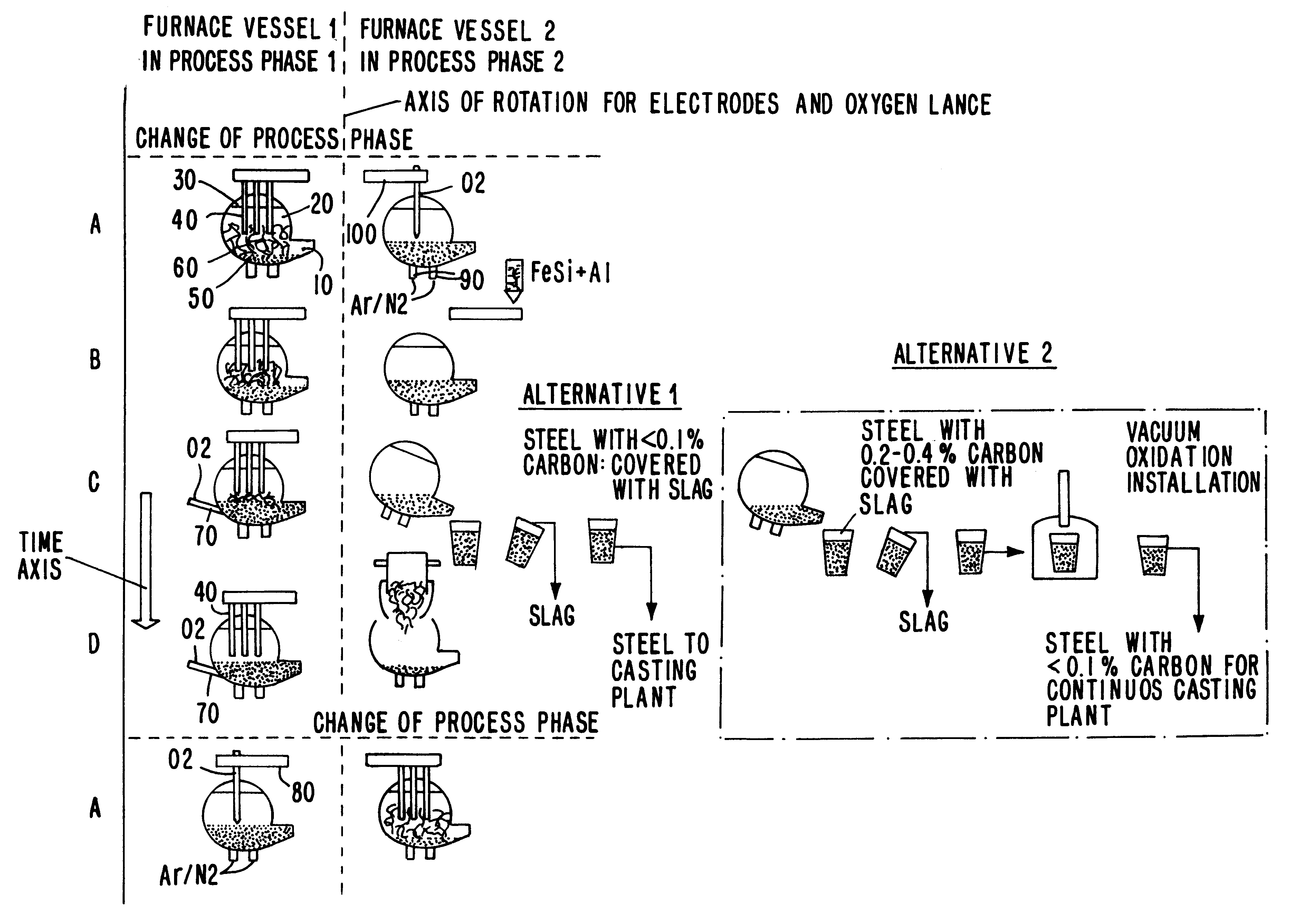
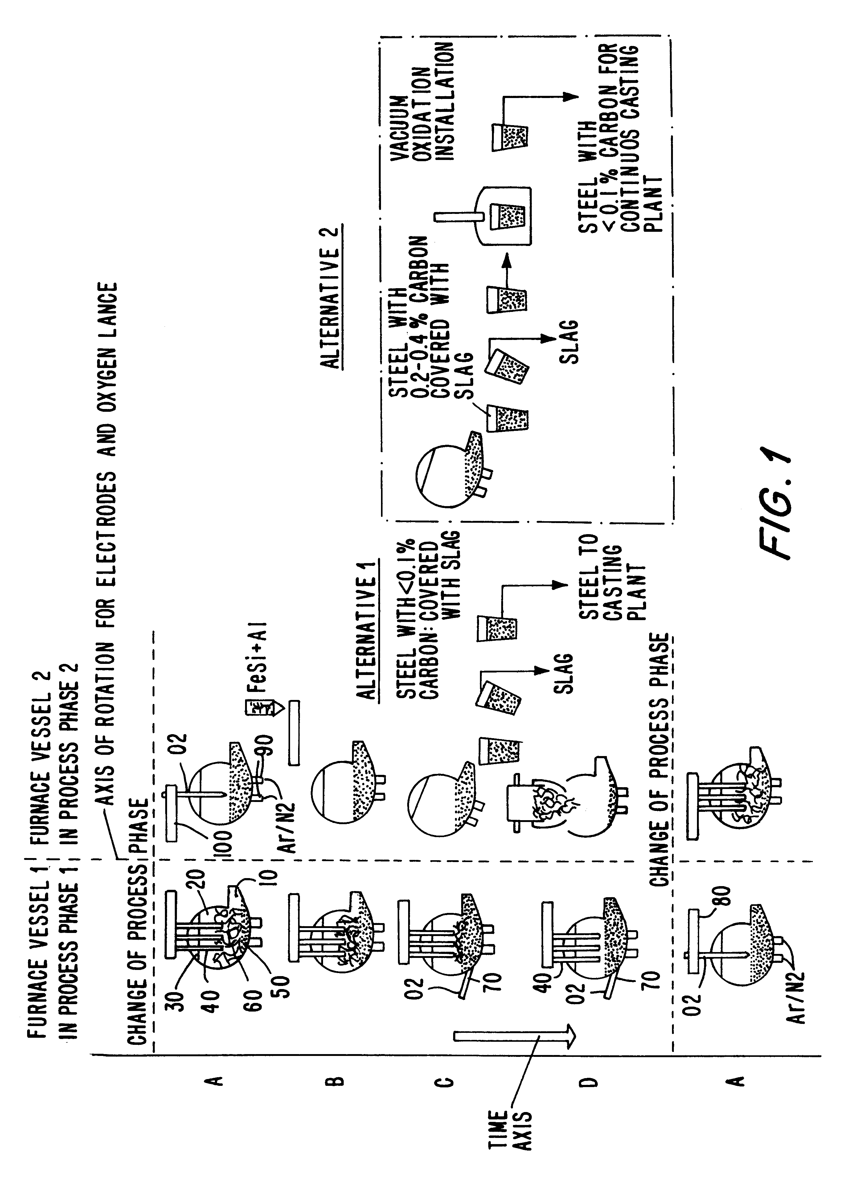
First, considering process phase 1, when furnace vessel 1 is at step A, there is a small liquid pool 50 in the furnace vessel 1 on which a newly poured charge 60 is located. The furnace vessel 1 is closed by means of a cover 30 through which electrodes 40 project into the upper vessel 20 of the furnace 1. In step B, the charge 60 is melted by electrical energy provided by the electrodes 40. In so doing, the liquid bath level 50 rises in the lower vessel 10 of the furnace 1. In step C, the charge 60 comprising essentially scrap, ferronickel, nickel, ferrochromium and other iron-containing metallic materials, is melted virtually completely to liquid base metal 50. When using high carbon-containing and / or high silicon-containing alloying means, oxygen can be blown in by means of a first lance 70, so that the silicon content is reduced.

In step D, the base material is completely melted, and the melt has a temperature of 1500.degree. C. to 1600.degree. C. In vessel 1, the electrode device...


PUM

PropertyMeasurementUnit
temperatureaaaaaaaaaa

Abstract

A process for producing stainless steels, particularly special steels containing chromium and chromium-nickel, in a smelting arrangement having at least two vessels, for supplying a steel foundry. A charge having mostly iron-containing raw scrap materials and partially carbon-containing alloy carriers is melted in a first vessel. At a temperature of 1460° C., the melt is decarburized by the injection of oxygen so as to reduce the carbon content to less than 0.3%. The melt is heated to a tapping temperature of between 1620° C. to 1720° C. and the carbon content is subsequently reduced to 0.1%. A second charge is melted in a second vessel simultaneously with the decarburizing of the first charge in the first vessel.

Description

1. Field of the InventionThe present invention is directed to a process for producing stainless steels, and particularly for producing special steels containing chromium and chromium-nickel, in a smelting arrangement having at least two vessels for supplying a steel foundry.2. Description of the Related ArtUsually, an electric furnace of conventional construction is used in the production of chromium-containing, and chromium-nickel-containing stainless steels. The electric furnace is constructed as a D.C. or A.C. furnace in which scrap and other iron-containing metallic raw material, e.g., pig iron or DRI (Direct Reduced Iron), are melted together with an adequate amount of alloying elements or alloy carriers. The raw or base material which is melted for this purpose is tapped off into a ladle at a temperature of 1670.degree. C. to 1700.degree. C. The ladle is subsequently emptied into a converter wherein the melt, which contains approximately 2.5% carbon and approximately 1% silico...

Claims


Application Information

Patent Timeline
Patent Type & Authority Patents(United States)
IPC IPC(8): C21C5/00C21C5/52C21C7/068
CPCC21C5/5264C21C7/0685Y02P10/20
Inventor ROSE, LUTZVORWERK, HARTMUTKAPPES, HORSTULRICH, KLAUS
Owner MANNESMANN AG
Why Eureka
Try Eureka