

Superabrasive tool and method of manufacturing the same
- Summary
- Abstract
- Description
- Claims
- Application Information
AI Technical Summary
Benefits of technology
Problems solved by technology
Method used
Image

Examples
example 1
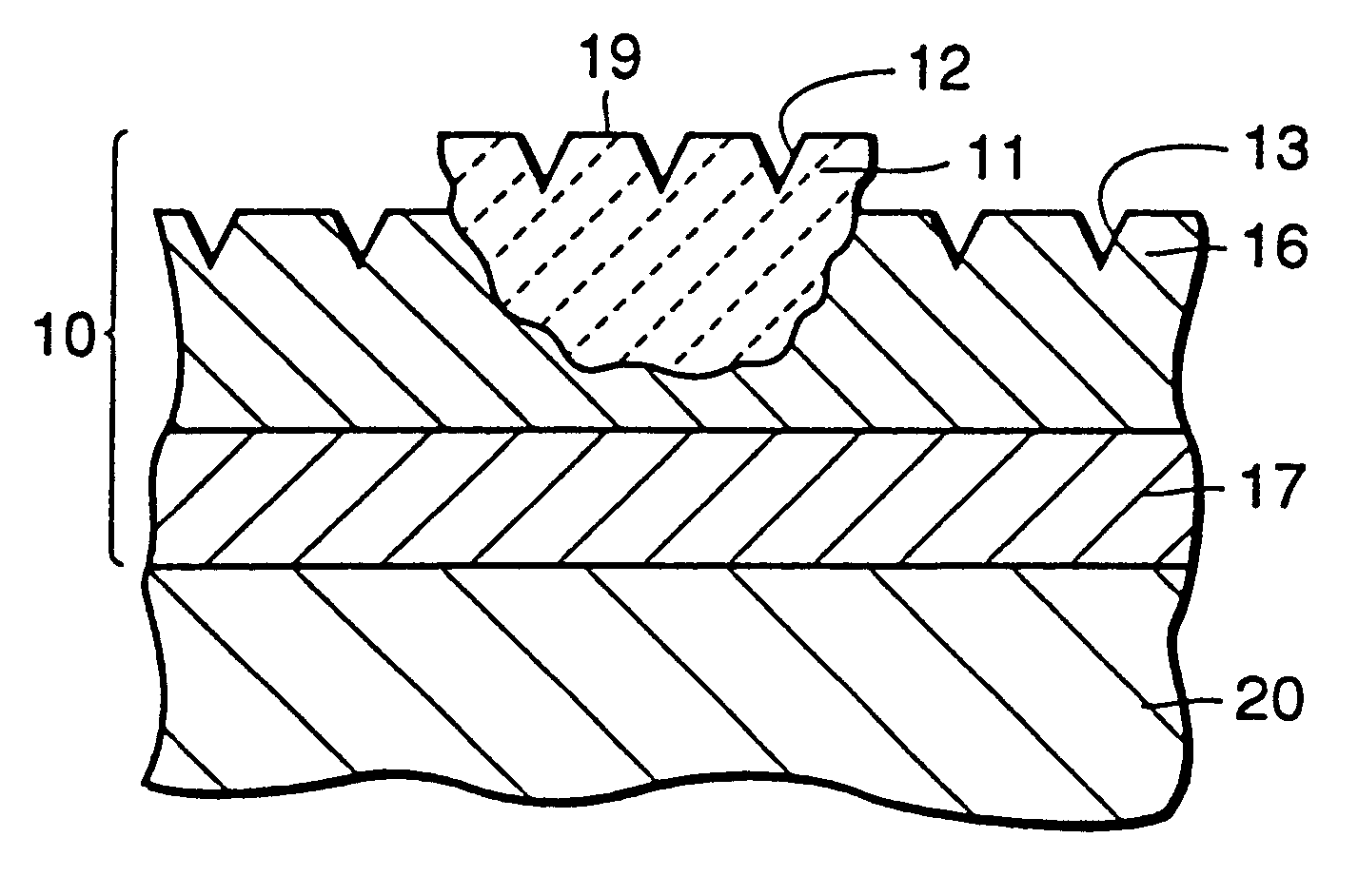
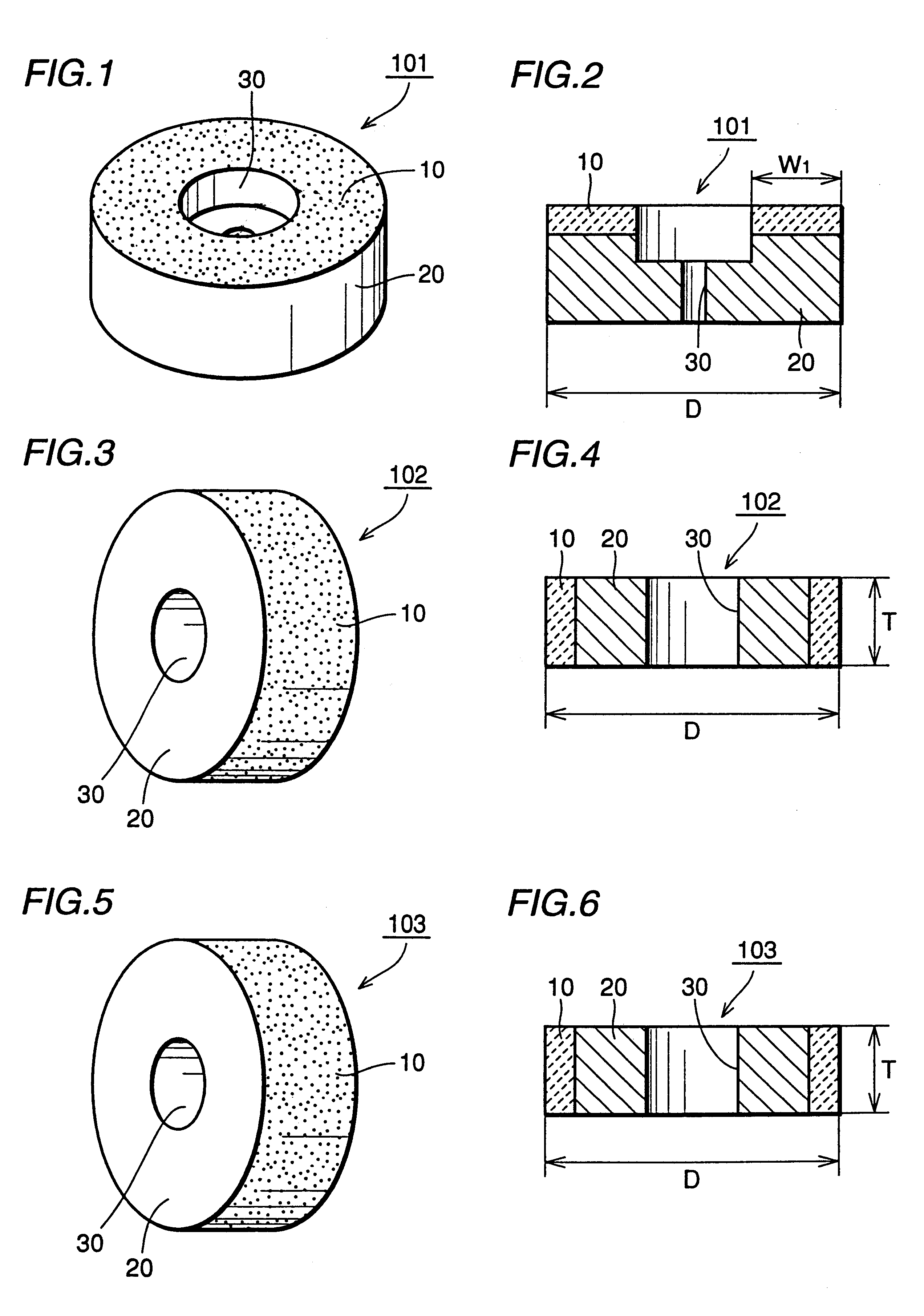
The cup-type superabrasive grindstone 101 shown in FIG. 1 and FIG. 2 was prepared. The diameter D of the grindstone was 125 mm, and the width W.sub.1 of the abrasive surface was 7 mm. Diamond grains of #18 / 20 in grain size (800 to 1000 .mu.m in grain size) were employed as the superabrasive grains. The superabrasive layer 10 was formed by holding and fixing the diamond grains on the base of the grindstone by nickel plating. Thereafter the surface of each superabrasive grain 11 projecting from the nickel plating layer 16 was trued (a thickness of about 30 .mu.m was removed from the grain 11) with a diamond grindstone of #120 in grain size for forming the flat surface 19, as shown in FIG. 23. A microphotograph (magnification: 40) showing a state after truing the abrasive surface is shown in FIG. 43.
Thereafter the surface of the superabrasive layer 10 was irradiated with the laser beam 50 from the laser beam machining unit 40 in the normal direction as shown in FIG. 11. As to the laser...
example 2
FIG. 45 is a diagram showing a longitudinal sectional side surface of a straight-type superabrasive grindstone 102 before performing truing. FIG. 46 and FIG. 47 are sectional views showing a superabrasive layer employed for illustrating manufacturing steps for substantially regularizing the amounts of projection of superabrasive grains. A manufacturing method for regularizing the amounts of projection of the superabrasive grains will now be described with reference to these drawings.
As shown in FIG. 46, superabrasive grains 11 consisting of diamond grains of #30 / 40 in grain size are spread and held in one layer on a surface of a mold 60 of carbon with a conductive adhesive layer 70 such as synthetic resin containing powder of copper. A copper plating layer 80 of 60 to 100 .mu.m in thickness was formed by dipping this mold 60 in a plating solution of copper as such or after hardening the resin by heating. Then, the plating solution was exchanged and a nickel plating layer 16 of 1.5 m...
example 3
The cup-type superabrasive grindstone 101 shown in FIG. 1 and FIG. 2 was prepared. The diameter D of the cup-type superabrasive grindstone 101 was 125 mm, and the width W.sub.1 of the abrasive surface was 7 mm. Diamond grains of #18 / 20 in grain size (800 to 1000 .mu.m in grain size) were employed as the superabrasive grains. These diamond grains were fixed to the base of the grindstone by a nickel plating layer as the holding layer.
Flat surfaces were formed by truing exposed surfaces of the diamond grains with a diamond grindstone of #120 in grain size so that projecting surfaces of the fixed diamond grains were on the same plane as the surface of the nickel plating layer. Thereafter continuous grooves were formed on the flat surfaces of the diamond grains serving as the superabrasive grains and the surface of the nickel plating layer serving as the holding layer by irradiating the flat surfaces with the laser beam 50 from the normal direction as shown in FIG. 11 while rotating the ...
PUM
| Property | Measurement | Unit |
|---|---|---|
| Grain size | aaaaa | aaaaa |
| Thickness | aaaaa | aaaaa |
| Electrical conductor | aaaaa | aaaaa |
Abstract
Description
Claims
Application Information