
Electrically conductive adhesive composition, electrically conductive adhesive sheet and use thereof

a technology of electrical conductivity and adhesive composition, which is applied in the direction of synthetic resin layered products, conductors, weaving, etc., can solve the problems of poor electromagnetic shield function, copper foil is not sufficiently durable in bending test, and the electromagnetic shield function is difficult to achieve a decrease in size and thickness, etc., to achieve excellent adhesion capability and electric conductivity, excellent shielding properties, and excellent flame retardancy

Inactive Publication Date: 2002-02-05
TOMOEGAWA PAPER CO LTD
View PDF5 Cites 56 Cited by
  • Summary
  • Abstract
  • Description
  • Claims
  • Application Information

AI Technical Summary

Benefits of technology

The electrically conductive adhesive composition and the electrically conductive adhesive sheet of the present invention have excellent adhesion capability and electric conductivity, and have excellent flame retardancy. The electromagnetic wave shield material to which the electrically conductive adhesive composition or the adhesive sheet is applied not only exhibits excellent shielding properties against electromagnetic waves in FPC but also is excellent in adhesion to FPC and flexibility. Further, it has a high flame retardancy of the V-1 to V-0 level.Further, due to the use of the tetrabromobisphenol A derivative, the electromagnetic wave shield material not only exhibits excellent shield properties against electromagnetic waves in FPC but also is excellent in adhesion to FPC, durability against a high-temperature and high-humidity environment and flexibility, and it further has a high flame retardancy of the V-1 to V-0 level.

Problems solved by technology

Since, however, a group of bundled shield cables in a larger number is used, it is difficult to attain a decrease in size and thickness.
However, there are caused problems that the electromagnetic wave shield function is poor since the copper foil is generally attached with an adhesive having the level of an insulator having a volume resistivity of 10.sup.7 .OMEGA.cm or more as an electric resistance, and that the copper foil is not sufficiently durable in a bending test and undergoes brittle fracture.
The above electromagnetic wave shield method is excellent, while it is not yet fully satisfactory as far as flame retardancy is concerned.
When it exceeds the above upper limit, the electric conductivity is low due to poor dispersion of the carbon.
When the primary particle diameter of the carbon is smaller than 15 nm, the carbon is liable to be dispersed poorly.
When it exceeds 60 nm, it is difficult to obtain a desired electric conductivity.
Further, when the above melting point is lower than 100.degree. C., there may be caused a problem that the initial adhesion strength of an electromagnetic-wave-shield-functioning flexible printed wiring board obtained by laminating the electromagnetic wave shield material on FPC is low, or that the flexible printed wiring board shows a decrease in adhesion when left at a high temperature or in a high-temperature and high-humidity environment.
The electromagnetic wave shield material formed a laminate of the electrically conductive adhesive sheet and an electrically conductive fiber sheet is morphologically likely to burn, and it does not easily arrive at the level of VTM-0 in the UL94 vertical combustion test, so that it is required to select the flame retardant from a limited range.
When the amount of the component (b) is smaller than 20 parts by weight, the tackiness on an adhesive surface increases, and handling of a sheet is difficult.
Further, the heat resistance of a cured product is low.
When the amount of the component (b) is larger than 500 parts by weight, the flexibility and the adhesion strength are low.
When the amount of the component (c) exceeds 100 parts by weight, the flexibility and the adhesion strength are low.
Further, when the amount of the component (d) is smaller than 1 part by weight, no sufficient flame retardancy can be obtained.
Further, when the amount of the component (e) is smaller than 1 part by weight, the adhesive may be unstable against deterioration under heat.
When the volume resistivity of the electrically conductive adhesive composition exceeds the upper limit of the above range, it is difficult to effectively leak the eddy current generated by electromagnetic waves to the grounding in the FPC layer, and the electromagnetic wave shield effect is insufficient.
When the above volume resistivity is smaller than the above lower limit, it is difficult to uniformly disperse the filler, and the strength of adhesion to FPC is low.
When it exceeds 500 .mu.m, the electric conductivity between the metal fiber sheet or the metal foil and FPC is deficient, so that the shielding effect against electromagnetic waves is low and further that the flexibility is low.
When the above thickness is less than 10 .mu.m, not only the electromagnetic wave shield capability is deficient, but also the sheet has poor tensile strength, so that handling of the sheet is difficult.
Further, when the above thickness exceeds 500 .mu.m, undesirably, the flexibility is low.
When the above thickness is smaller than the above lower limit, handling of the metal foil is difficult.
When the above thickness exceeds the above upper limit, the flexibility is low.

Method used


Image

  • Electrically conductive adhesive composition, electrically conductive adhesive sheet and use thereof
  • Electrically conductive adhesive composition, electrically conductive adhesive sheet and use thereof
  • Electrically conductive adhesive composition, electrically conductive adhesive sheet and use thereof

Examples


example 1

An electrically conductive adhesive composition containing the following components was prepared.

Acrylonitrile-butadiene copolymer (trade name: NIPOL1001, supplied by Nippon Zeon Co.,Ltd.) 100 parts

Bisphenol A type resol type phenolic resin (trade name: Shonol CKM-908, supplied by Showa Highpolymer Co.,Ltd.) 100 parts

Carbon Powder (trade name: Denka Black HS-100, supplied by Denki Kagakii Kogyo K.K., DBP oil absorption 140 ml / 100 g) 60 parts

High-molecular-weight hindered phenol-containing antioxidant (trade name: Adekastab AO-60, supplied by Asahi Denka Kogyo K.K.) 6 parts

The above electrically conductive adhesive composition was applied to a release PET film having a thickness of 38 .mu.m, and the composition was dried in a hot-air-circulating dryer at 130.degree. C. for 3 minutes, to obtain an electrically conductive adhesive sheet having an adhesive layer thickness of 30 .mu.m. The sheet had a volume resistivity of 3.0 .OMEGA..multidot.cm.

75 Parts of a stainless steel fiber havin...

examples 2-10

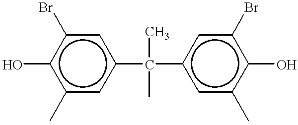
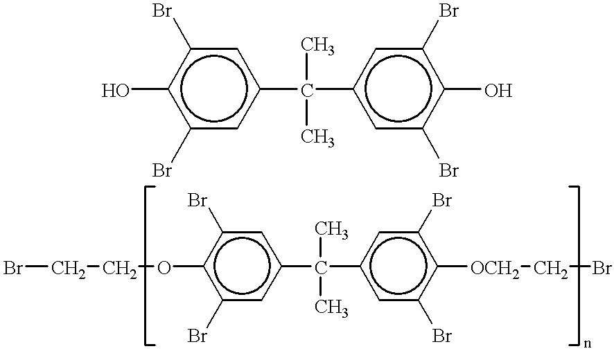
An electrically conductive adhesive sheet, an electromagnetic wave shield material and FPC to which these were applied were produced in the same manner as in Example 1 except that the bromine-containing flame retardant was replaced with a material shown in Table 1.

examples 11-15

An electrically conductive adhesive sheet, an electromagnetic wave shield material and an electromagnetic-wave-shield-functioning flexible printed wiring board were produced in the same manner as in Example 1 except that the stainless steel fiber sheet was replaced with an electrically conductive fiber sheet shown in Table 2.


PUM

PropertyMeasurementUnit
Fractionaaaaaaaaaa
Percent by massaaaaaaaaaa

Abstract

An electrically conductive adhesive composition which has flexibility and folding endurance and is feasible for use as a shield against electromagnetic waves from a flexible printed circuit, comprises 100 parts by weight of (a) an acrylonitrile-butadiene copolymer, 20 to 500 parts by weight of (b) a phenolic resin and / or an epoxy resin, 1 to 100 parts by weight, per 100 parts by weight of the components (a) and (b) in total, of (c) an electrically conductive filler and 1 to 50 parts by weight, per 100 parts by weight of the components (a) and (b) in total, of (d) a bromine-containing flame retardant.

Description

The present invention relates to an electrically conductive adhesive composition and an electrically conductive adhesive sheet having flexibility and folding endurance feasible for use as a shield against electromagnetic waves in a flexible printed circuit (FPC), an electromagnetic wave shield material formed by integrating these with an electrically conductive fiber sheet, and an electromagnetic-wave-shield-functioning flexible printed wiring board formed by laminating the electromagnetic wave shield material on a flexible substrate.DESCRIPTION OF THE PRIOR ARTWith regard to an electromagnetic wave shield of a cable for connecting electronic machines or devices, conventionally, a group of shield cables obtained by braiding individual conductive cables is used. Since, however, a group of bundled shield cables in a larger number is used, it is difficult to attain a decrease in size and thickness.Electronic machines, devices and peripheral hardware are recently decreasing in size and ...

Claims


Application Information

Patent Timeline
IPC IPC(8): H01B1/24H05K1/02H05K1/09
CPCH01B1/24H05K1/095H05K1/0218Y10T442/109Y10T442/2475A44B1/02A44B1/04
Inventor KITAHARA, HIROSHIHIGASHI, KENSAKU
Owner TOMOEGAWA PAPER CO LTD
Learn More