
Liquid crystal alignment film, method of manufacturing the film, liquid crystal display using the film and method, and method of manufacturing the liquid crystal display

a technology of liquid crystal alignment and alignment film, which is applied in the direction of thin material processing, material nanotechnology, instruments, etc., can solve the problems of poor uniformity of alignment film in surface step portions and display defects

Inactive Publication Date: 2002-04-09
PANASONIC CORP
View PDF24 Cites 36 Cited by
  • Summary
  • Abstract
  • Description
  • Claims
  • Application Information

AI Technical Summary

Benefits of technology

The present invention was carried out in order to solve the above-mentioned conventional problems, and thus has the object of providing a method for forming an alignment film used in a liquid crystal display panel highly efficiently, uniformly and thinly without performing a rubbing treatment as conventionally performed, and providing a method for producing a display panel employing the same.
Furthermore, when heat is applied so as to react thermoreactive groups before or after radiating energy beams so as to react and crosslink the energy beam sensitive groups, the heat resistance of the alignment of the alignment film was improved. Electron beams, X rays, or ultraviolet rays are usable as the energy beams, but ultraviolet rays provided a higher practicability in an actual production process.

Problems solved by technology

Therefore, there is a serious problem in that uniformity in the alignment film is poor in surface step portions or for a large area panel (such as a 14 inch display).
Moreover, since rubbing is performed, defects are generated in the TFTs, and debris generated by rubbing causes defects in display.

Method used


Image

  • Liquid crystal alignment film, method of manufacturing the film, liquid crystal display using the film and method, and method of manufacturing the liquid crystal display
  • Liquid crystal alignment film, method of manufacturing the film, liquid crystal display using the film and method, and method of manufacturing the liquid crystal display
  • Liquid crystal alignment film, method of manufacturing the film, liquid crystal display using the film and method, and method of manufacturing the liquid crystal display

Examples


example 1-2

The same experiment as Example 1 was performed, except that CH.sub.3 (CH.sub.2).sub.14 SiCl.sub.3 and NC(CH.sub.2).sub.14 SiCl.sub.3, which contain a linear hydrocarbon group comprising one functional group for controlling the surface energy of a film at the terminal and Si, were used as the silane-based surfactant after the exposure of the entire face (they were mixed at a mole ratio of 1:1).

As a result of the reaction with the chlorosilane-based surfactant, a monomolecular chemisorption film was formed selectively in the portion on the surface of the substrate where hydroxyl groups have been generated by exposure. This monomolecular film was chemically bonded thereto via siloxane bonds in a thickness of about 1.5 nm. The critical surface energy of the chemisorption film was about 27 mN / m.

Furthermore, two substrates in this state were used so as to be set so that the chemisorption films were facing each other. Thus, a liquid crystal cell having a 20 micron gap was assembled so that...

example 2

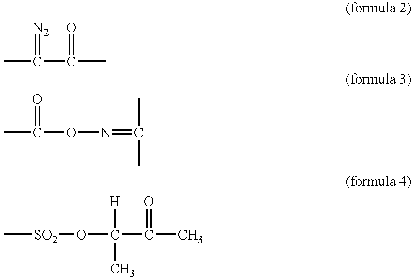
First, a positive resist 22 (e.g., AZ1400 manufactured by SIHPLEY) mainly composed of a novolak resin and comprising a naphthoquinone diazido based photosensitizer containing the group represented by (formula 2) was applied onto a surface of a glass substrate 21 provided with TFT always having pixel electrodes on their surfaces to a thickness of 0.1 to 0.2 .mu.m and dried so as to form a film. The critical surface energy of the film was 28 mN / m. Next, using a photomask 23 for dividing each pixel (a polarizing plate or a diffraction grating may be disposed on the mask for dividing the pixel for the purpose of improving the alignment property of the adsorption film), the positive resist was exposed to light of 435 nm at 100 mJ / cm.sup.2 (FIG. 5). As a result, the resist reacted with moisture in the air in an exposed portion 22' so as to proceed the reaction represented by (formula 5). At this time, since --COOH group 25 generated by the exposure contains active hydrogen (FIG. 6, which ...

example 3

After exposure and before the process of chemisorption of the molecules comprising linear hydrocarbon groups in Example 1, the substrate was immersed in an adsorption solution prepared by dissolving a compound containing a plurality of chlorosilyl groups in a dry atmosphere. Then, a dehydrochlorination reaction was effected between hydroxyl groups of the carboxyl groups generated on the surface of the resist and chlorosilyl groups of the compounds containing a plurality of chlorosilyl groups. Thereafter, when a reaction with water was allowed to be effected, the remaining chlorosilyl groups changed to hydroxyl groups, so that a chemisorption film comprising a large number of hydroxyl groups on its surface was formed.

For example, SiCl.sub.4 was used as the silyl compound containing a plurality of chloro groups, and dissolved in Fluorinert FC40 (3M product name) so as to prepare an adsorption solution. Then, the exposed substrate was immersed in the adsorption solution. As a result, s...


PUM


Abstract

A positive resist mainly composed of a novolak resin and comprising a naphthoquinone diazido-based photosensitizer as an energy beam sensitive resin (e.g., a photosensitive resin) is applied in a thickness of 0.1 to 0.2 mum to a surface of a glass substrate 1 provided with transparent electrodes and dried so as to form a photosensitive film. Next, using a mask, the film is exposed to ultraviolet rays (365 nm). Then, moisture in the air reacts with the resist in an exposed portion 2', thereby generating -COOH groups, with which CH3(CH2)18SiCl3 is allowed to react so as to cause a dehydrochlorination reaction, thereby forming a monomolecular chemisorption film 6 comprising carbon chains 8. This film is used as an alignment film. Thus, the present invention provides a method for producing a uniform and thin alignment film for use in a liquid crystal display panel with a high efficiency without performing a rubbing treatment, and a method for producing a display panel using the same.

Description

The present invention relates to an image display apparatus employing liquid crystal and a method for producing such an image display apparatus. More specifically, the present invention relates to a liquid crystal alignment film used for a flat display panel employing liquid crystal for displaying images on television (TV) and computers or the like, and a method for producing such a liquid crystal alignment film, and also relates to a liquid crystal display apparatus employing the same and a method for producing such a liquid crystal display apparatus.Conventionally, an apparatus used as a color liquid crystal display panel generally includes liquid crystal that is injected between two substrates provided with counter electrodes arranged in a matrix via a liquid crystal alignment film formed by rotary-coating a polyvinyl alcohol or a polyimide solution with a spinner or the like.For example, the following device was proposed. Thin film transistor (TDF) arrays having pixel electrodes...

Claims


Application Information

Patent Timeline
IPC IPC(8): G02F1/13G02F1/1337C09K19/00
CPCB82Y30/00G02F1/133719G02F1/133788Y10T428/1005G02F2001/133765Y10T428/1014C09K2323/023C09K2323/02G02F1/133765G02F1/1337
Inventor OGAWA, KAZUFUMI
Owner PANASONIC CORP
Learn More