
Method for controlling dopant profiles

a technology of dopant profiles and dopants, applied in the direction of material analysis using wave/particle radiation, instruments, manufacturing tools, etc., can solve the problems of difficult to deliver rare earth, alumina, other dopants using conventional processes, chemical vapor deposition, etc., and achieve the effect of improving the performance of optical fiber or planar waveguides

Inactive Publication Date: 2002-10-22
CORNING INC
View PDF13 Cites 52 Cited by
  • Summary
  • Abstract
  • Description
  • Claims
  • Application Information

AI Technical Summary

Benefits of technology

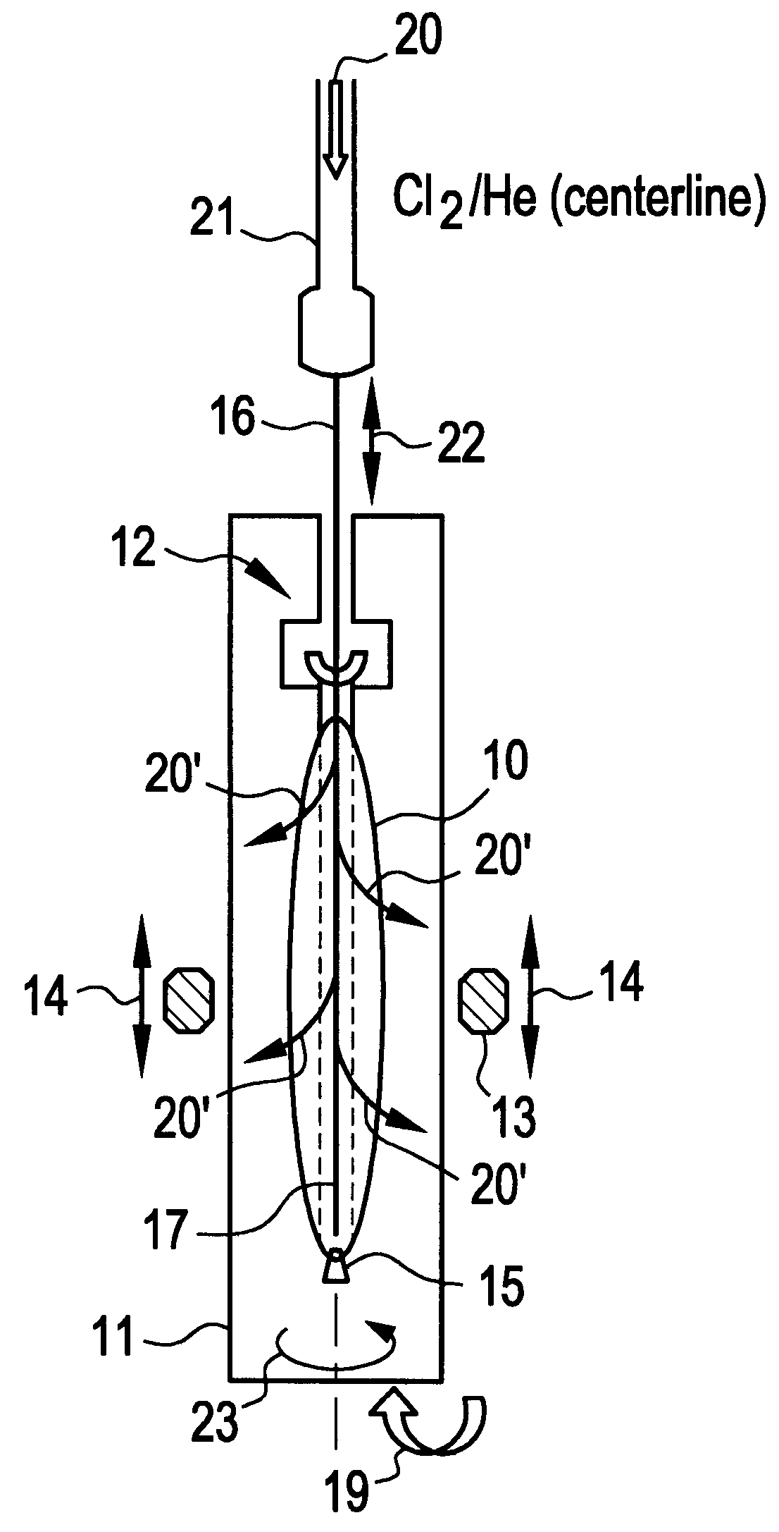
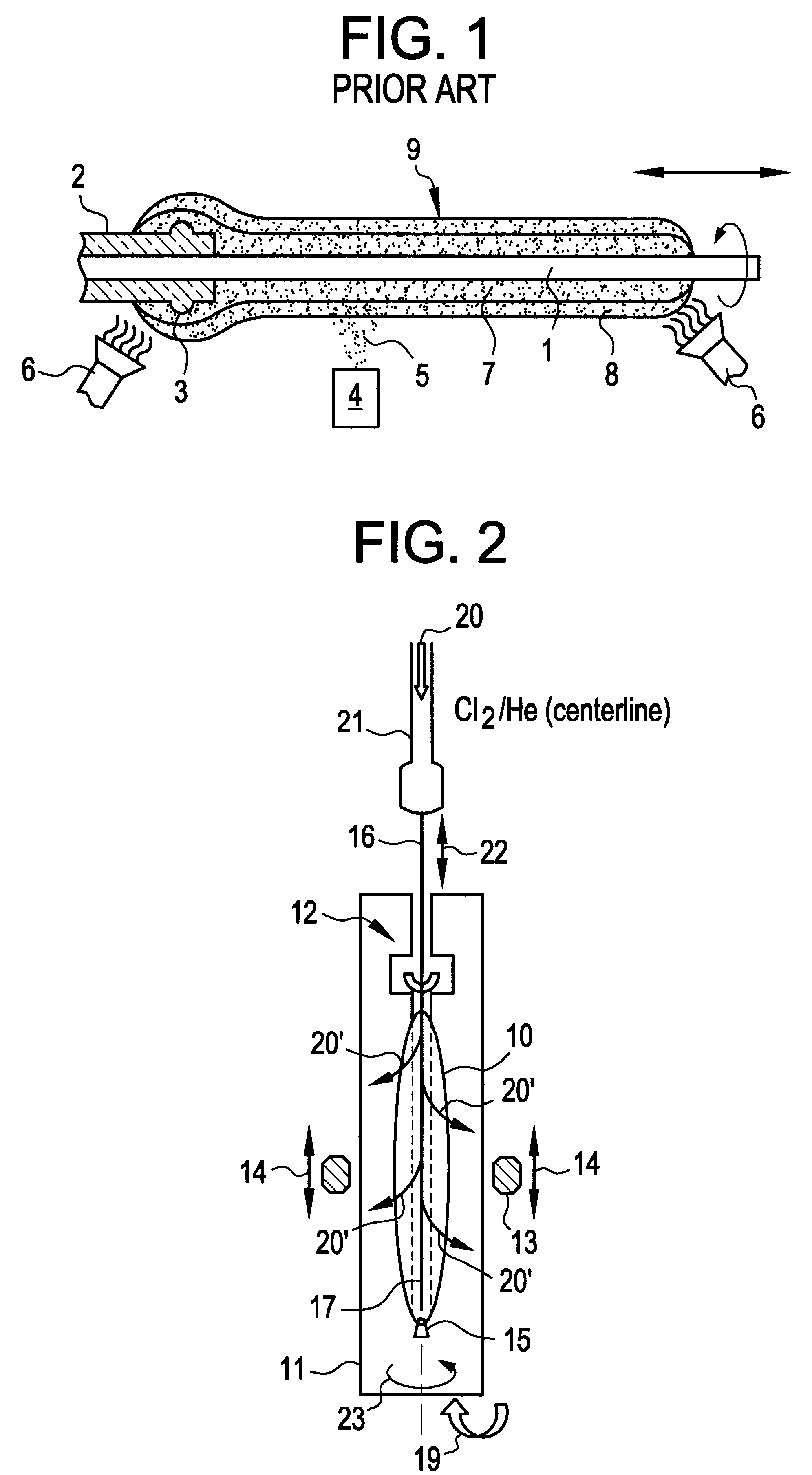
Several important advantages are achieved by making glass articles, such as planar waveguides, optical waveguide preforms, or waveguide core preforms (also referred to as canes or rods), using the methods of the invention. One advantage is an increase in the overall concentration of a second dopant into a glass blank containing a first dopant, such as GeO.sub.2 and / or TiO.sub.2. A further advantage of the present invention is to effect the penetration of the second dopant that extends radially, i.e. from the center of the preform, to a greater degree than is generally achieved with other known methods. Yet a further advantage of the present invention is providing a cane or preform that exhibits a substantially uniform dopant profile across its radius. These advantages enhance the performance of the optical fiber or planar waveguide for glass optical fiber amplifiers, lightwave optical circuits, or other applications.

Problems solved by technology

These properties make it difficult to deliver rare earth, alumina, and other dopants using conventional processes, such as chemical vapor deposition, that are amenable to dopants, such as Ge or Ti, having relatively high vapor pressure precursors.
Yet another problem that occurs in vapor deposition of dopants that sublimate rather than vaporize is the likelihood of bubble formation.
These methods, although effective, are also not without drawbacks.
If the particles within the porous preform are too loosely bound, the preform can disintegrate or crack within the solution.
Thus, the solution doping method requires extra processing steps, adds cycle time, and potentially introduces manufacturing defects into the fiber process.

Method used


Image

  • Method for controlling dopant profiles
  • Method for controlling dopant profiles
  • Method for controlling dopant profiles

Examples


example 2

Except for differences specified below, a process similar to Example 1 was used to form an Al.sub.2 O.sub.3 --GeO.sub.2 doped, step index profile optical fiber preform. A soot blank comprising approximately 16 wt % GeO.sub.2 (or double the GeO.sub.2 content as Example 1) was formed using an OVD process. The blank had a bulk density of 0.322 g / cc. During the doping step, the parameters for the gas flow down the centerline line remained the same as in Example 1. However, the upward flow of He gas through the muffle was doubled to 40 slpm and the flow of O.sub.2 through the muffle was omitted. For the 1 hour doping cycle, the furnace temperature was 567.degree. C. at the start of the doping cycle, decreased to 464.degree. C. mid-cycle, and finished at 410.degree. C. by the cycles completion. Almost all of the original 1.106 g of Al wire was consumed during the doping cycle.

FIG. 6 provides the electron microprobe data for a cane of the consolidated and redrawn glass. Referring to FIG. 6...

example 3

Except for the differences specified below, a process similar to Example 1 was used to form an Al.sub.2 O.sub.3 --SiO.sub.2 preform and an Al.sub.2 O.sub.3 --GeO.sub.2 --SiO.sub.2 preform.

For the Al.sub.2 O3--SiO.sub.2 preform, the SiO.sub.2 soot blank, which was formed via an OVD process, had a bulk density of 0.330 g / cc. The doping cycle was conducted for a time duration of 1 hour. The furnace temperature was initially 515.degree. C. at the start of the doping cycle, decreased to 454.degree. C. mid-cycle, and finished at 395.degree. C. at the completion of the cycle. During the doping cycle, a constant downward flow of 35 sccm Cl.sub.2 and 0.32 slpm He gas passed through the furnace handle and along the centerline of the soot blank. At the same time, an upward flow of about 40 slpm He gas passed through the muffle of the furnace. A total of about 1.1035 g of Al wire reacted during the 1 hour doping cycle. The drying and consolidation steps were the same as in Example 1. The consol...

example 4

Except for the differences specified below, a process similar to Example 1 was used to form an Al.sub.2 O.sub.3 --TiO.sub.2 --SiO.sub.2, parabolic profile optical fiber preform. A soot blank comprising approximately 1.5 wt % TiO.sub.2 was formed using an OVD process. The doping cycle was conducted for a time duration of 1 hour. The temperature of the furnace during the doping cycle was approximately between 400.degree. C. and 600.degree. C. During the doping cycle, a downward flow of 35 sccm Cl.sub.2 gas and 0.32 slpm He gas flowed through the centerline and an upward flow of 40 slpm He gas passed through the furnace muffle. Approximately 1.0649 gram of Al reacted during the doping cycle.

The consolidation step consisted of a 1 hour drying step and a shorter time duration sintering step. During the drying step, a continuous flow of 0.9 slpm Cl.sub.2 gas and 9 slpm He gas passed through the muffle. During the sintering step, a continuous flow of 2 slpm O.sub.2 gas and 2 slpm He gas pa...


PUM

PropertyMeasurementUnit
temperatureaaaaaaaaaa
densityaaaaaaaaaa

Abstract

The present invention discloses novel methods for fabricating glass articles, particularly optical fiber glass preforms, which may contain alumina, yttrium, lanthanum, erbium, or other rare earth metals as dopants. The glass articles made in accordance with the present invention exhibit radially uniform dopant profiles relative to conventional dopant methods. In addition, the overall concentration of the dopant is increased relative to analogous dopant methods.

Description

The present invention provides a method for controlling the concentration profile of dopants incorporated into a glass article. More particularly, the present invention relates to an improved method of doping an optical fiber preform with dopants that are not readily incorporated during the initial fabrication process.Optical fibers are typically drawn from glass preforms. An optical fiber preform is generally comprised of a central core and an outer cladding layer. The central core, for the most part, has a higher refractive index than the cladding layer. When the preform is drawn into an optical fiber, the difference in refractive indices between the core and cladding layers allows the propagation of the optical signal within the core. Optical fiber preforms and waveguides are composed primarily of high purity silica glass.Variations in the refractive index are obtained by adding dopants to layers within the central core or surrounding cladding layer. Certain dopants such as the o...

Claims


Application Information

Patent Timeline
Patent Type & Authority Patents(United States)
IPC IPC(8): C03B37/014C03C13/00C03C13/04G02B6/12
CPCC03B37/01446C03B37/0146C03C13/046C03B2201/28C03B2201/30C03B2201/31C03B2201/34C03B2201/36C03B2201/40C03B2201/42C03B2201/54G02B2006/12038G02B2006/12166
Inventor CHU, POLLY W.MOORE, LISA A.PIERSON-STULL, MICHELLE D.
Owner CORNING INC
Learn More