Eureka AIR delivers breakthrough ideas for toughest innovation challenges, trusted by R&D personnel around the world.

Separator for a fuel cell

a fuel cell and separator technology, applied in the direction of cell components, final product manufacturing, sustainable manufacturing/processing, etc., can solve the problems of uneven molding, affecting moldability, and it is impossible to obtain a molded member (separator) which is correct in shap

Inactive Publication Date: 2002-10-22
NIPPON PILLAR PACKING CO LTD
View PDF4 Cites 27 Cited by
  • Summary
  • Abstract
  • Description
  • Claims
  • Application Information

AI Technical Summary

Benefits of technology

It is another object of the invention to enhance flatness of an end face contacting with an electrode without being affected by the molding accuracy of the whole of a separator, whereby the contact resistance with respect to an electrode can be sufficiently lowered.
It is a further object of the invention to lower the contact resistance with respect to an electrode and, at the same time, enhance the bending elasticity of a separator, so that also damage, such as crack due to vibrations, can be prevented from occurring.
According to the invention having the above-mentioned characteristic configuration, a bondcarbon compound of a complex in which the composition ratio of the thermosetting resin is set to be large or 10 to 40% is used, and hence elongation and fluidity during a molding process are improved so that, even when injection molding means having good productivity is employed, a molded member (separator) of a desired shape can be surely obtained. While ensuring such excellent moldability, the contact resistance between the molded member and an electrode which is affected at the highest degree by the increased content of the resin can be greatly lowered by the presence of the conductive film with which the end face contacting with the electrode is coated. Therefore, it is possible to attain an effect that, while improving the productivity by the employment of injection molding means having excellent moldability, the conductivity of the separator as a whole can be remarkably improved and predetermined performance of a fuel cell can be sufficiently exerted.
In the separator for a fuel cell of the invention, the conductive film may be thin or have a thickness of 10.mu.m or smaller, preferably, 3.mu.m or smaller. According to this configuration, the flatness accuracy of the conductive film can be enhanced without being affected by the molding accuracy of the separator itself, so that the actual contact area can be made larger. This cooperates with the low specific resistance of the film itself to reduce the contact resistance with respect to an electrode to an extremely low level.
As the graphite powder which is useful in the invention, powder of graphite of any kind, including natural graphite, artificial graphite, carbon black, kish graphite, and expanded graphite may be used. In consideration of conditions such as cost, the kind of graphite can be arbitrarily selected. In the case where expanded graphite is used, particularly, a layer structure is formed by expanding the volume of the graphite as a result of heating. When molding pressure is applied, layers can twine together to be firmly bonded to one another. Therefore, a complex and hence a separator can be enhanced in bending elasticity so that damage, such as cracks due to vibrations, can be prevented from occurring. Consequently, expanded graphite is most effective.

Problems solved by technology

When a bondcarbon compound in which the content of a thermosetting resin is reduced as described above is used, however, elongation and fluidity of the bondcarbon compound during a molding process are lowered to impair the moldability, and easily cause molding unevenness.
As a result, it is impossible to obtain a molded member (separator) which is correct in shape.
Furthermore, height uniformity and flatness of an end face contacting with an electrode are largely affected by the accuracy of a molding die.
Even when the specific resistance of the bondcarbon compound itself is lowered, therefore, the contact resistance with respect to an electrode is high, and hence it is difficult to sufficiently improve the conductivity of a separator.
As a result, the specific resistance of a bondcarbon compound itself is high, and the contact resistance with respect to an electrode which largely affects the performance of a fuel cell is inevitably raised, so that the problem of reduced conductivity is unavoidably produced.

Method used


Image

  • Separator for a fuel cell
  • Separator for a fuel cell
  • Separator for a fuel cell

Examples


Embodiment Construction

Hereinafter, an embodiment of the invention will be described with reference to the accompanying drawings.

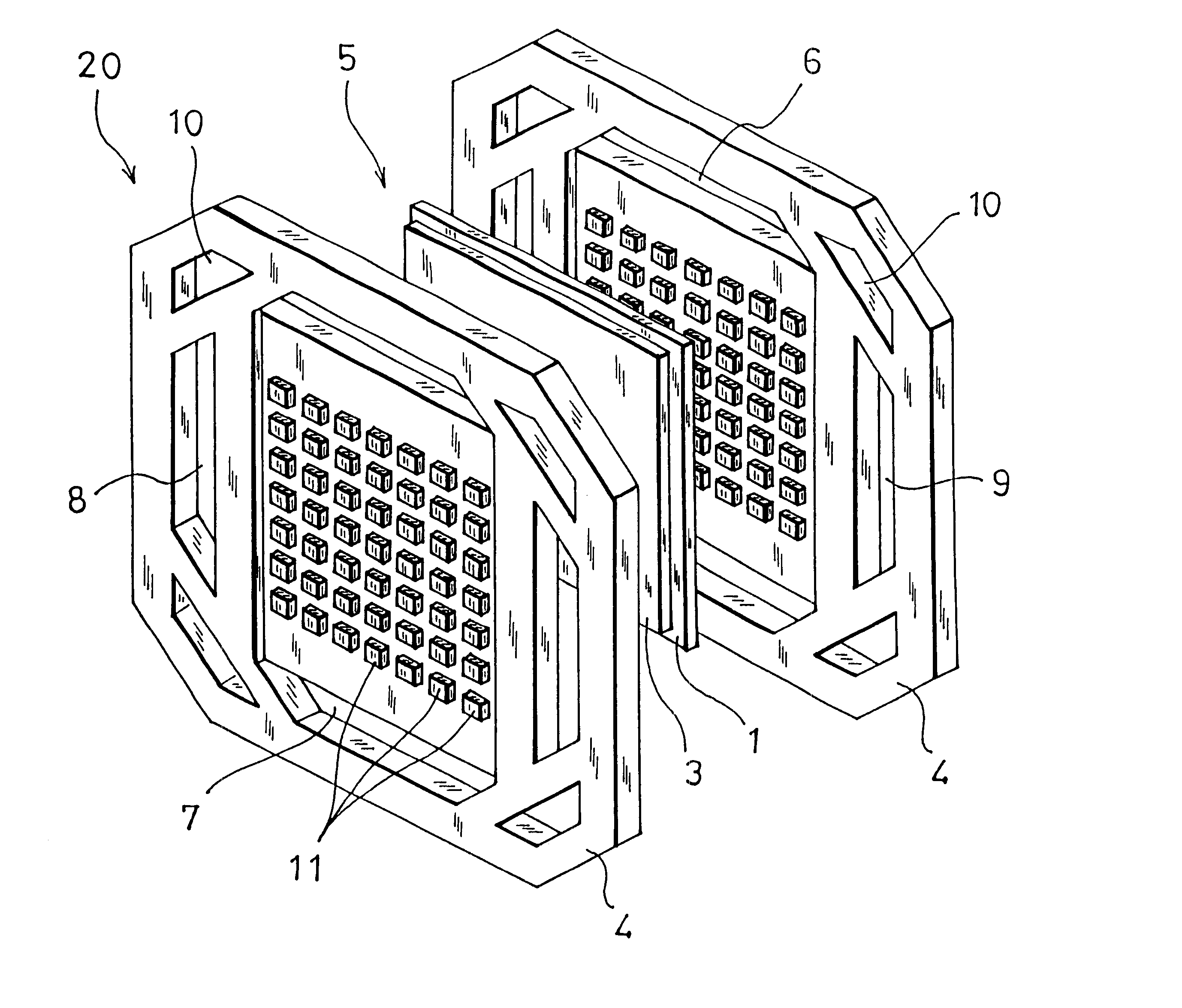
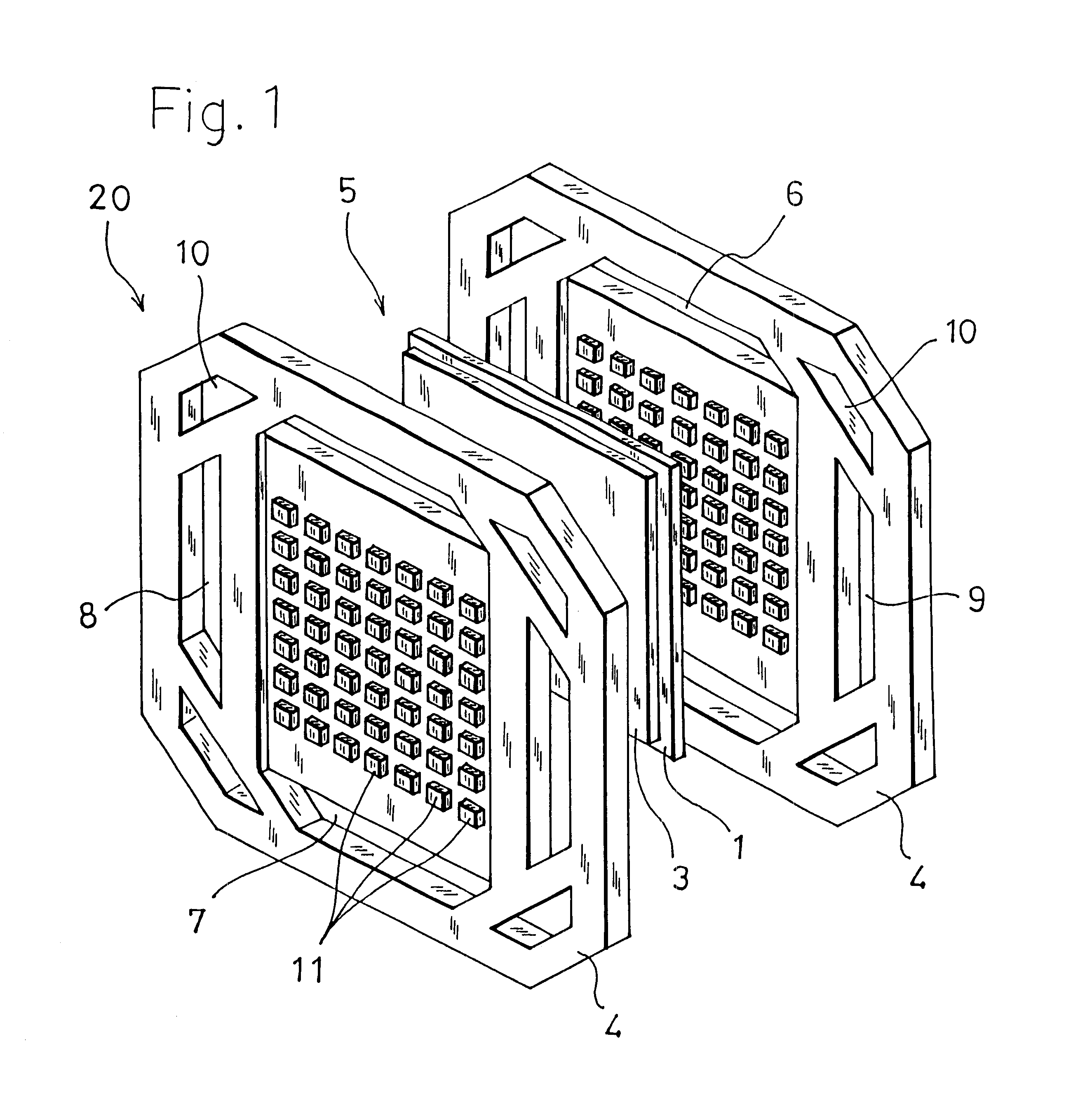
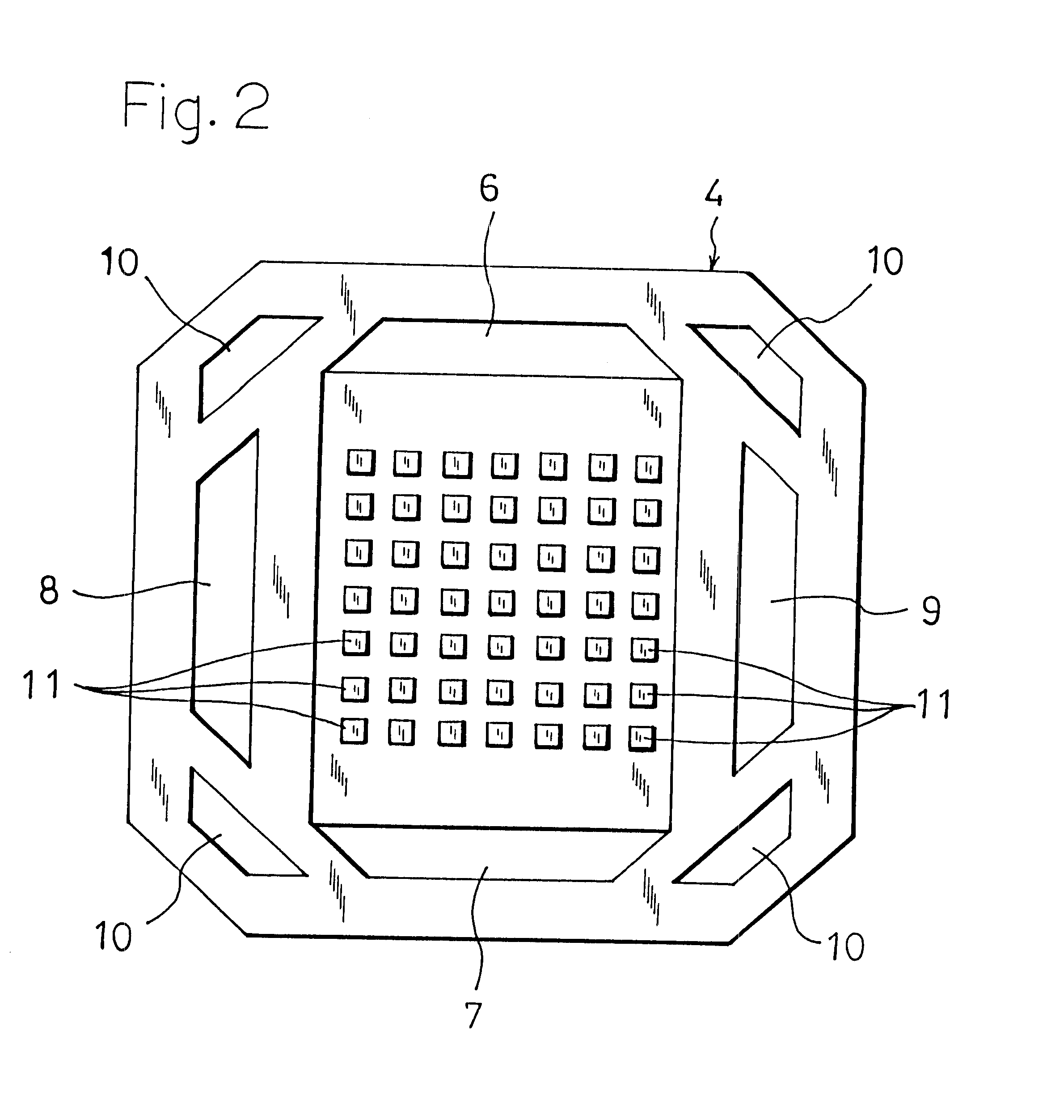
First, the configuration and the operation of a solid polymer electrolyte type fuel cell having the separator of the invention will be briefly described with reference to FIGS. 1 to 3.

The solid polymer electrolyte type fuel cell 20 has a stack structure in which plural unit cells 5 are stacked and collector plates (not shown) are respectively placed on both ends. Each of the unit cells 5 is configured by: an electrolyte membrane 1 which is an ion exchange membrane made of, for example, a fluororesin; an anode 2 and a cathode 3 which are formed by carbon cloth woven of carbon filaments, carbon paper, or carbon felt, and which sandwich the electrolyte membrane 1 to constitute a gas diffusion electrode having a sandwich structure; and separators 4 which sandwich the sandwich structure.

In each of the separators 4 on the sides, as shown in FIG. 2, fuel gas holes 6 and 7 for a fuel ga...


PUM

PropertyMeasurementUnit
thicknessaaaaaaaaaa
thicknessaaaaaaaaaa
elongationaaaaaaaaaa

Abstract

In a separator for a fuel cell according to the invention, a separator is formed by a molding a bondcarbon compound in which a composition ratio of graphite powder is set to 60 to 90%, and a composition ratio of a thermosetting resin is set to 10 to 40%, and at least a top end face of each of a number of ribs contacting the surface of an anode or a cathode is coated with a conductive film made of a material which is lower in specific resistance than the bondcarbon compound. According to this configuration, while excellent moldability and high productivity are ensured by the use of the bondcarbon compound containing a larger content of a resin, the contact resistance with respect to an electrode is lowered so that the conductivity of the whole can be improved, and predetermined performance of a fuel cell can be surely exerted.

Description

1. Field of the InventionThe present invention relates to a separator for a fuel cell which is mainly used as a cell for an electric vehicle, and more particularly to a separator for a fuel cell of the electrolyte type in which a unit cell that is a unit constituting the cell is configured by: sandwiching a gas diffusion electrode having a sandwich structure wherein an electrolyte membrane configured by an ion exchange membrane is interposed between electrodes (an anode and a cathode); and forming fuel gas passages for a fuel gas containing hydrogen and oxidant gas passages for an oxidant gas containing oxygen between the separators, and the electrodes of both the sides.2. Description of the Prior ArtIn a fuel cell, a fuel gas and an oxidant gas are respectively supplied to an anode and a cathode, so that, in the anode and the cathode, electrochemical reactions indicated by the formulae:H.sub.2.fwdarw.2H.sup.- +2e.sup.- (1)(1 / 2)O.sub.2 +2H.sup.- +2e.sup.-.fwdarw.H.sub.2 O (2)occur, ...

Claims


Application Information

Patent Timeline
Patent Type & Authority Patents(United States)
IPC IPC(8): H01M8/02H01M2/14H01M8/10
CPCH01M8/0226H01M8/0228H01M8/0213H01M8/0221Y02E60/522Y02E60/50H01M50/446H01M8/0223H01M50/463H01M8/0247H01M50/449H01M50/489H01M50/414H01M50/403Y02E60/10Y02P70/50
Inventor YOSHIDA, TSUNEMORI
Owner NIPPON PILLAR PACKING CO LTD
Why Eureka
Eureka Blog
Learn More