

Magnetic recording disk
a magnetic layer and recording technology, applied in the field of magnetic recording disks, can solve the problems of coexistence of fine and coarse grains, limit the control of the distribution of crystal grain size of the information recording magnetic layer,
- Summary
- Abstract
- Description
- Claims
- Application Information
AI Technical Summary
Benefits of technology
Problems solved by technology
Method used
Image

Examples
embodiment 1
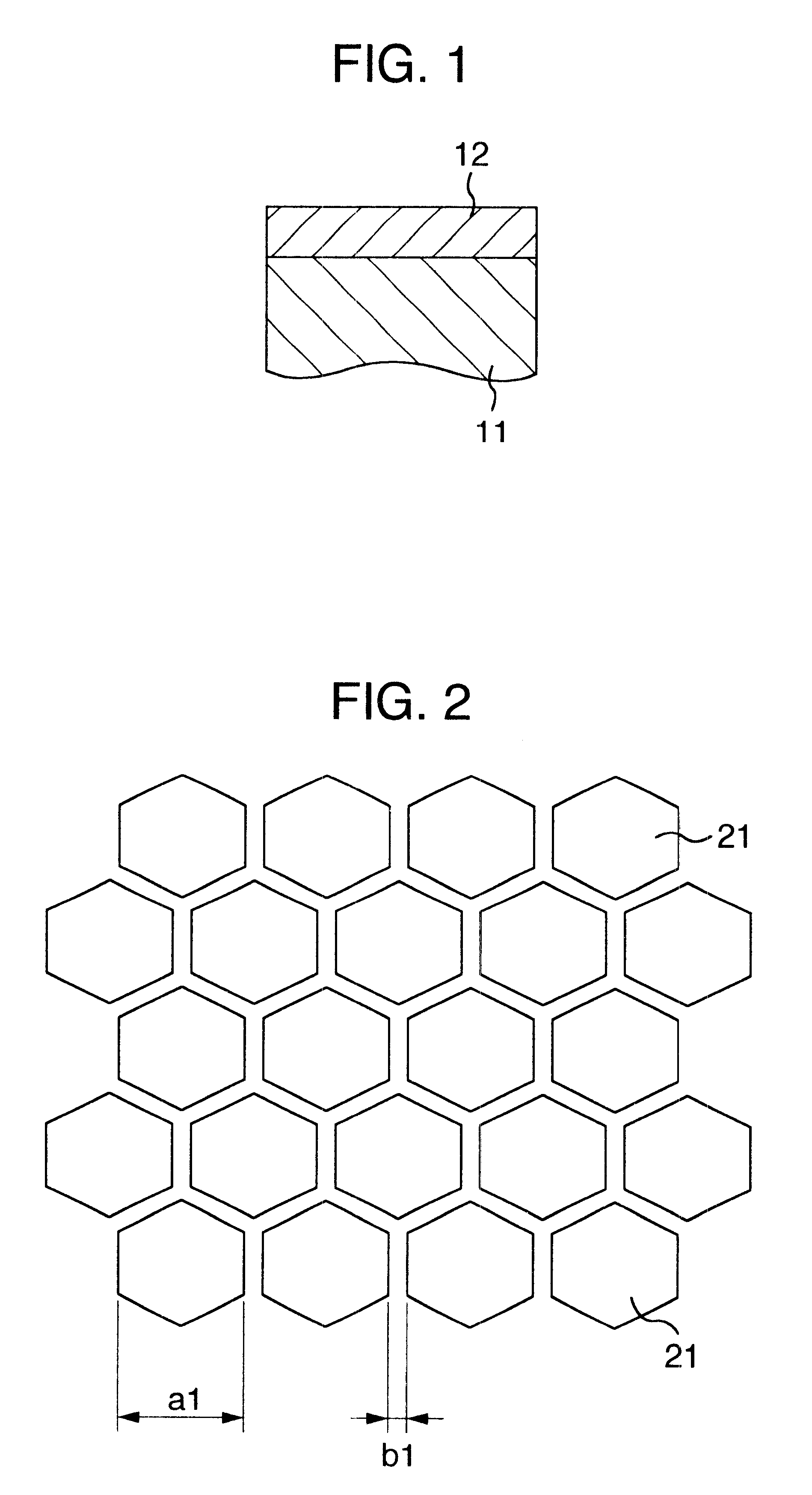
FIG. 1 is a schematic view showing a cross-sectional structure of a platelike body fabricated according to this embodiment. An inorganic compound layer 12 was deposited over a glass substrate 11 to a thickness of 30 nm by sputtering. In depositing the inorganic compound layer 12, a target was used which was made by mixing a CoO powder and a SiO.sub.2 powder in a molar ratio of 2:1 and sintered. Pure argon (Ar) was used for a discharge gas. In the sputtering, the Ar pressure was 3 mTorr and the RF power applied was 500 W / 150 mm.phi..
FIG. 2 is a schematic view showing the surface of the deposited inorganic compound layer 12 as observed by a transmission electron microscope (TEM). Kirino As shown in this figure, the inorganic compound layer 12 has a honeycomb structure in which regular hexagonal crystal grains 21 are regularly arrayed two-dimensionally.
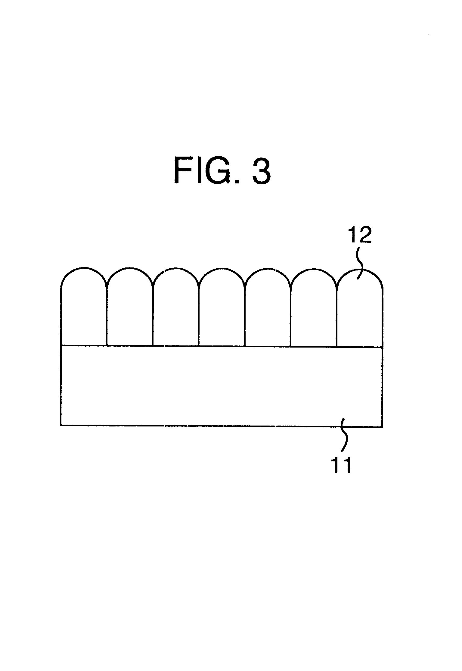
FIG. 3 is a schematic view showing the cross section of the inorganic compound layer 12 as observed by the TEM. As shown in FIG. 3, the...
embodiment 2
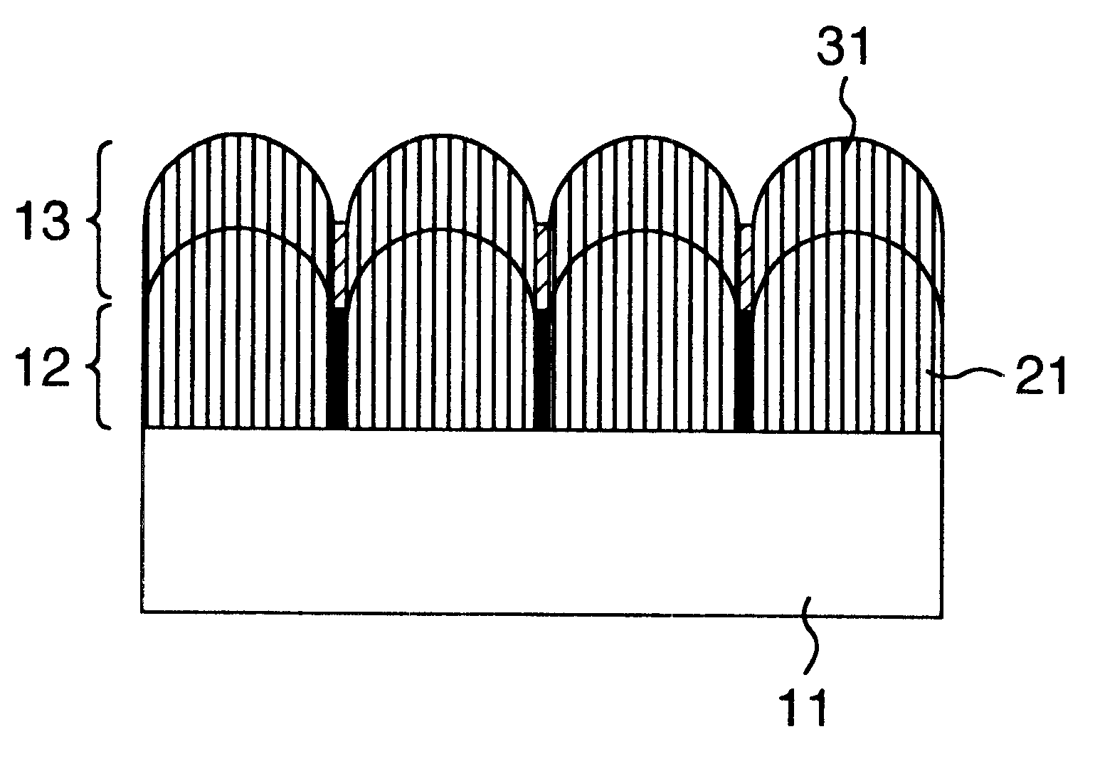
A magnetic recording disk was manufactured by depositing a magnetic layer over the inorganic compound layer formed in the embodiment 1. FIG. 5 is a schematic cross section of a magnetic recording disk according to this embodiment.
Over a glass substrate 2.5" in diameter, which is the substrate 11 of the magnetic recording disk, an inorganic compound layer 12 was deposited to a thickness of 30 nm by the method similar to that of the embodiment 1. This thickness is determined considering an overall inner stress in the magnetic recording medium and is enough to prevent peeling from the substrate 11. This inorganic compound layer 12 has the structure explained in the embodiment 1. That is, as shown in FIG. 2, the layer 12 has a honeycomb structure in which almost regular hexagonal crystal grains 21 made of cobalt oxide are regularly arranged in a two-dimensional pattern, with amorphous SiO.sub.2 present in the boundaries between the crystal grains 21. The grain size distribution of the c...
embodiment 3
Next, we will describe a magnetic recording disk in which the lattice constant of crystal grains of the inorganic compound layer formed over the substrate is more than 10% different from the lattice constant of crystal grains of the magnetic layer. FIG. 8 shows a schematic cross section of a magnetic recording disk manufactured in this embodiment.
A glass substrate 41 of 2.5" in diameter was used as the substrate of the magnetic recording disk. A mixture of CoO powder and ZnO powder in a molar ratio of 3:1 was used as a target and an inorganic compound layer 42 was deposited by sputtering over the substrate 41 under the same conditions as in the embodiment 1 to a thickness of 30 nm. This thickness is determined considering an overall inner stress in the magnetic recording medium and is enough to prevent peeling from the substrate 11.
The observation of the surface of the inorganic compound layer 42 by TEM revealed a honeycomb structure in which, as shown in FIG. 2, almost regular hexa...
PUM
| Property | Measurement | Unit |
|---|---|---|
| thickness | aaaaa | aaaaa |
| thickness | aaaaa | aaaaa |
| width | aaaaa | aaaaa |
Abstract
Description
Claims
Application Information