Eureka AIR delivers breakthrough ideas for toughest innovation challenges, trusted by R&D personnel around the world.

Mass spectrometer system including a double ion guide interface and method of operation

Inactive Publication Date: 2003-03-04
THERMO FINNIGAN
View PDF9 Cites 72 Cited by
  • Summary
  • Abstract
  • Description
  • Claims
  • Application Information

AI Technical Summary

Benefits of technology

It is an object of the present invention to provide a mass spectrometer system employing an ion source with multiple ion guides configured and operated to convert adduct ions into sample ions and a method of operating multiple ion guides to convert adduct ions into sample ions to thereby increase the analyte ions current and sensitivity of the mass spectrometer system.
A DC voltage source is connected to provide a potential difference between the first lens and the first multipole ion guide or between interchamber lens and the second multipole ion guide or both which defines the ion's translational kinetic energy as it enters the second multipole ion guide. The ion's translational kinetic energy is chosen such that at the vacuum pressure of the second interface chamber adduct ions are converted into sample ions by collision induced dissociation without fragmentation of sample ions whereby the sample ion current entering the analyzer is increased, thereby increasing the sensitivity of the mass spectrometer system.
There is provided a method of operating a mass spectrometer system in which an analyzer in a vacuum chamber analyzes ions formed in an atmospheric pressure ionization source. The system includes first and second multipole ion guides disposed in serial first and second evacuated chambers immediately preceding the analyzer. The method comprises applying a DC voltage between the ion lens preceding either the first or the second multipole ion guide to provide translational kinetic energy to the adduct ions sufficient to dissociate any adduct ions at the pressure of the second chamber without fragmenting the sample ions whereby to increase the sample ion current directed into the analyzer and the sensitivity of the mass spectrometer system.

Problems solved by technology

Furthermore, the adduct ions which enter into the mass analyzer complicates the mass spectrum and make the identification of mass peaks more difficult.

Method used


Image

  • Mass spectrometer system including a double ion guide interface and method of operation
  • Mass spectrometer system including a double ion guide interface and method of operation
  • Mass spectrometer system including a double ion guide interface and method of operation

Examples


Embodiment Construction

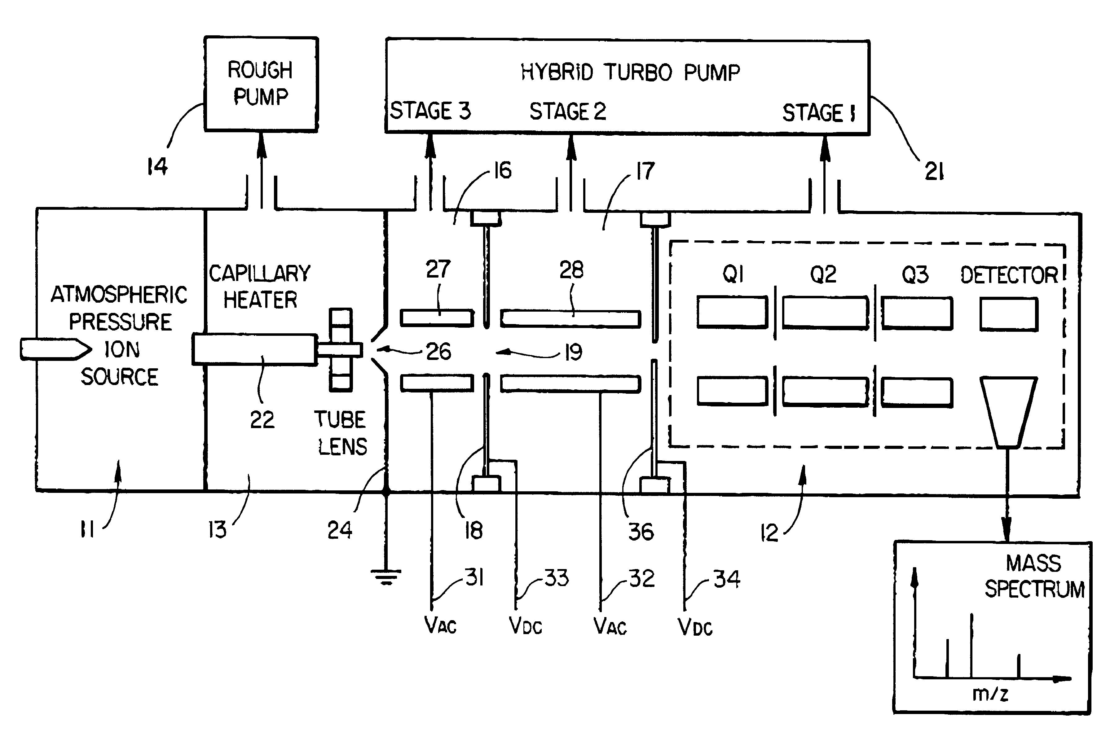
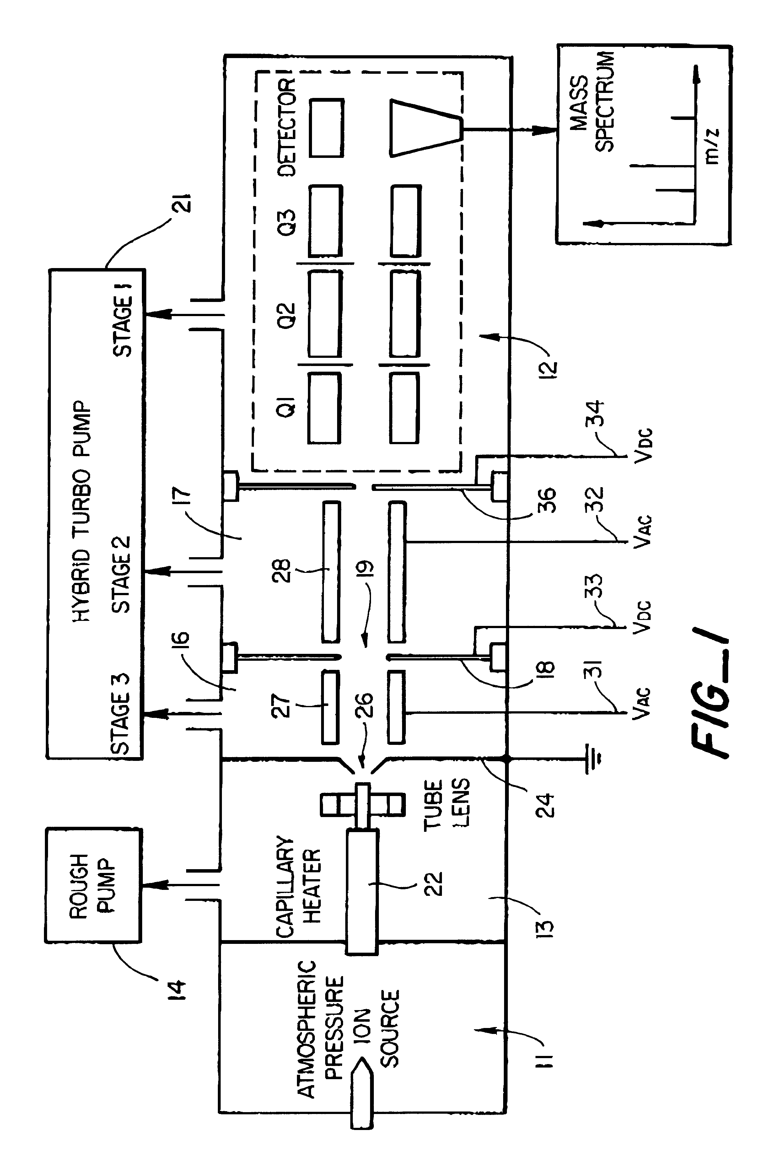
Referring to FIG. 1, an atmospheric pressure ion source in chamber 11 is interfaced to a tandem mass analyzer 12 via three vacuum pumping stages. The first stage 13 which has the highest pressure is evacuated by an oil-filled rotary vane vacuum pump 14. Other types of vacuum pumps may also be used for this stage, such as a diaphragm pump or scroll pump. A typical pressure for first stage 13 is between 1 and 2 Torr. The second and third stages 16 and 17 are separated by a lens 18 with an orifice 19, which in one example was 1.5 mm in diameter, and can be evacuated by a hybrid or compound turbomolecular pump 21 which includes both turbomolecular and molecular drag pumping stages, and may have multiple inlets into each of these pumping stages, or by individual vacuum pumps (not shown). As will be explained in accordance with the present invention, the pressure in chamber 16 is below 500 mTorr, preferably below 250 mTorr, and more preferably below 175 mTorr; and the pressure in chamber ...


PUM


Abstract

There is described an interface for delivering ions generated in an ion source into a mass analyzer in a chamber under vacuum pressure. In particular, the interface employs two consecutive ion guides operated to dissociate adduct ions formed in the ion source or high pressure regions of the interface between the ion source and the mass analyzer, thus improving the limit of detection or limit of quantitation of the mass analyzer by increasing the analyte ion current.

Description

This invention relates generally to mass spectrometry, and more particularly to mass spectrometers employing atmospheric pressure ion sources such as electrospray or atmospheric pressure chemical ionization. More particularly, the invention relates to the use of two consecutive ion guides between the ion source and the mass analyzer to dissociate adduct ions, thus increasing the ion current for the analytically useful molecular species.Generally, the interface between the atmospheric pressure ion source and the mass analyzer includes a capillary tube or other restrictive aperture which determines ion and gas throughput between the atmospheric pressure ionization region and a lower pressure region. The ions are drawn through the capillary or other restrictive aperture and directed to a downstream conical skimmer with a small aperture through which the sample ions flow. A tube lens or other electrostatic or electrodynamic focusing element may be associated with the capillary to force ...

Claims


Application Information

Patent Timeline
IPC IPC(8): H01J49/04H01J49/42H01J49/02H01J49/34H01J49/06G01N27/62H01J49/26
CPCH01J49/044H01J49/067H01J49/063
Inventor TANG, KEQISCHOEN, ALAN E.DUNYACH, JEAN-JACQUES
Owner THERMO FINNIGAN
Why Eureka
Eureka Blog
Learn More