Multimode optical fiber with a higher order mode removing function

a multi-mode optical fiber and function technology, applied in the field of multi-mode optical fibers, can solve the problems of not being able to meet the conditions of low-loss connection of plural optical fibers, the square root of the relative refractive index difference .delta..sup.1/2 cannot be increased, and the degree of freedom is increased

Inactive Publication Date: 2003-03-18
THE FUJIKURA CABLE WORKS LTD
View PDF31 Cites 41 Cited by
  • Summary
  • Abstract
  • Description
  • Claims
  • Application Information

AI Technical Summary

Benefits of technology

The present invention was conceived in view of the above-described circumstances and has as its objective the provision of an optical fiber having (A) a relatively large A.sub.eff, (B) low loss, (C) an absolute value for dispersion of around several ps / km / nm in the 1.55 .mu.m band, and (D) a relatively small bending loss sensitivity in the environment in which the optical fiber is employed.
Since it enables propagation over a broad band, it is preferable to have a small value for the slope of dispersion with respect to wavelength, i.e., the dispersion slope. This is particularly true in the case of a fiber employed in wavelength multiplex transmissions. This is because when optical signals of various wavelengths are transmitted in the employed wavelength band, their propagation states tend to become uniform when the dispersion slope is small. In the present invention, there is an increased degree of freedom with respect to the design parameters. As a result, there is greater freedom permitted when setting the fiber parameters, even in the case where designing an optical fiber having a low dispersion slope that is applied as a wavelength multiplex transmission fiber.

Problems solved by technology

As may be understood from Equation (2) above, the disadvantage of this step-index single mode fiber is that, in order to fulfill single mode conditions for a given wavelength .lambda., the product of core radius a (or core diameter 2a) and the square root of the relative refractive index difference .DELTA..sup.1 / 2 cannot be increased.
When the MFD is small, however, it is not possible to satisfy the conditions for low-loss connection of plural optical fibers.
When this type of design is executed, however, the refractive index difference is small, and the mode is large and spreads out from the core center.
As a result, if only a slight bend (i.e., a microbend) is applied to in the fiber, loss readily occurs as the energy of the propagating mode passes through the cladding and is radiated to the outside.
However, in a design in which two or more modes propagate in this way, the following problems may occur if the higher order mode does not quickly attenuate.
Thus, in this wavelength band, a step-index single mode fiber in which V is 2.4.about.3.0 has a large dispersion and is not very suitable for high-speed transmission.
For this reason, if even a slight bend is applied to the fiber, the energy of the propagating mode is radiated to the outside, and loss readily occurs.
Thus, it is known to be extremely difficult to design a dispersion shifted fiber which simultaneously satisfies this bending loss sensitivity and a dispersion shift to the 1.55 .mu.m band.
A problem occurs in long-distance transmission in which, when a sufficiently amplified large power optical signal is transmitted over a long distance, the signal waveform of the optical signal becomes distorted due to the influence of nonlinear effects.
This problem occurs irrespective of whether or not wavelength multiplex transmission is present.
Since the change in the instantaneous frequency becomes larger as modulation becomes faster, this becomes linked to the dispersion in the optical fiber and causes a large waveform distortion.
It is possible to conceive of an extremely large number of four-wave combinations as the number of wavelength multiplexes increases, so that many of these mutually interact to cause a deterioration in the quality of communication.
However, on the other hand, a dispersion value that is too small is inconvenient from the perspective of nonlinear effects.

Method used


Image

  • Multimode optical fiber with a higher order mode removing function
  • Multimode optical fiber with a higher order mode removing function
  • Multimode optical fiber with a higher order mode removing function

Examples


example 1

FIG. 6 is a graph showing the results of a simulation of the relationship between the normalized propagation constant and the normalized frequency in the example of a multimode optical fiber having the step-refractive index distribution shown in FIG. 5(a). In this multimode optical fiber, the relative values of the refractive indices of center part 1a and stepped part 1b are 0.80 and 0.06 (units: %). When the radius of center part 1a is set to 1, then the radius of stepped part 1b is 5.

The upper limit VC11 for a normalized frequency within limits that permit elimination of LP mode propagation is around 8. In the case of a design that actively does not permit LP11 mode propagation, such as conventional designs, the limits for V must be smaller than the aforementioned. Thus, freedom of design is extremely narrow. In contrast, by applying the present invention, a design is possible within the range of from 8 to 15 approximately, where the LP02 mode, which is the third mode, is generate...

examples 2 , 3

Examples 2, 3

FIGS. 10 and 11 are graphs showing the results for a simulation of the relationship between the normalized propagation constant bmn and the normalized frequency V of the multimode optical fibers from Examples 2 and 3 respectively.

As shown in their respective graphs, Examples 2 and 3 are provided with the step-refractive index distribution shown in FIG. 5(a).

In Example 2, the relative refractive indices of center part 1a and stepped part 1b based on the refractive index of the cladding are 0.80% and 0.08% respectively. These values are 0.80% and 0.12% respectively in Example 3. In addition, when the radius of center part 1a is 1, then the radius of stepped part 1b is 5 in the case of both Examples 2 and 3.

example 4

FIG. 12 is a graph showing results for a simulation of the relationship between the normalized propagation constant bmn and the normalized frequency V of the multimode optical fiber of Example 4.

As shown in this graph, the multimode optical fiber of Example 4 is provided with the refractive index distribution shown in FIG. 5(e). The relative refractive indices of center part 5a, ring part 5c and cladding 11 based on the refractive index of intermediate part 5b are 0.61%, 0.31% and 0.02% respectively. In addition, when the radius of center part 5a is 1, then the radius of intermediate part 5b is 2.8 and the radius of ring part 5c is 3.9.


PUM


Abstract

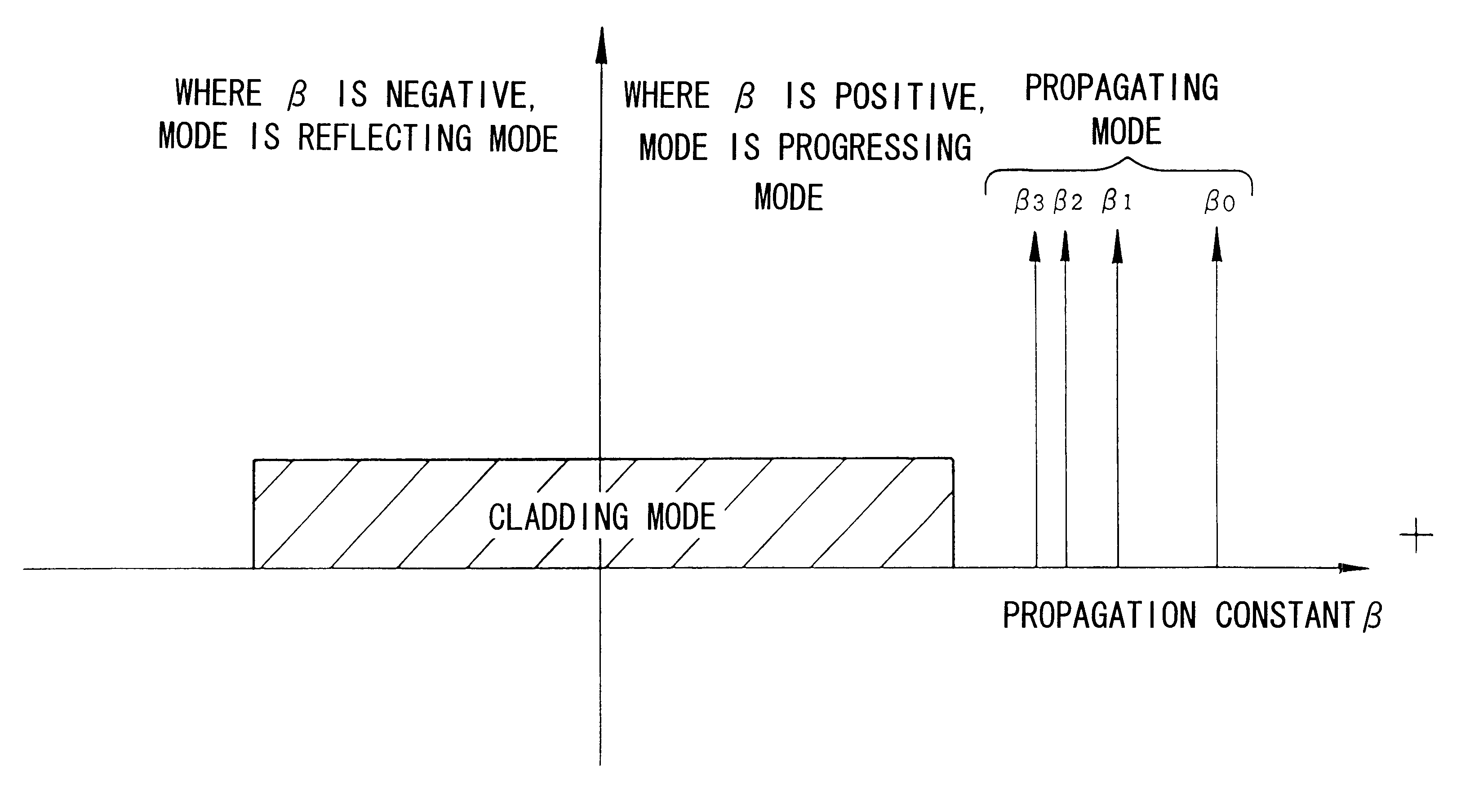
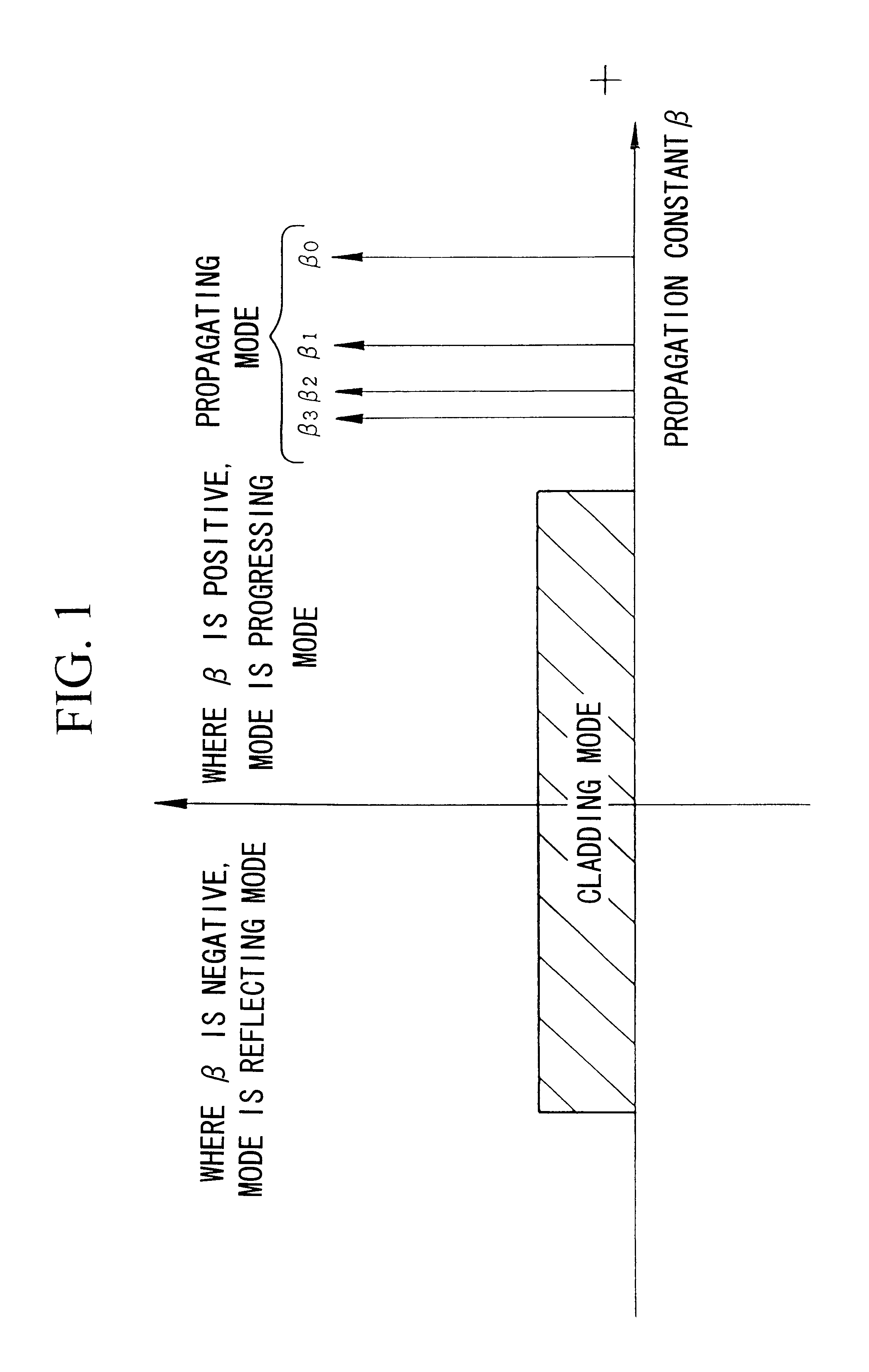
The present invention's multimode optical fiber is characterized in that the propagating modes include a mode the lowest and second or higher order modes; and the difference between the propagation constants of the lowest order mode and the second order mode is 2-fold or more than the difference between the propagation constants of adjacent modes that are second order or higher order modes. Due to this design, single mode propagation becomes possible once the modes have propagated over a specific distance. As a result, it is possible to relax the conventional single mode conditions, enabling the fiber parameters to be set relatively freely.

Description

The present invention relates to an optical fiber used for relatively long-distance transmission, that is mainly applicable to super high-speed transmission or to multiplex transmissions with a high wavelength density.Single mode fibers are familiar examples of conventional optical fibers used in high-speed transmission. These single mode fibers for high-speed transmission are usually formed of quartz glass, where the term as employed here shall mean quartz glass having silicon dioxide as the main component. In addition, the quartz glass forming the optical fiber core in this specification is understood to be quartz glass in which at least 50 wt % or more of the composition is silicon dioxide.A single mode fiber of the simplest structure has a step-refractive index distribution. This step-index single mode fiber is designed with a cladding which is around and in contact with a core. The core has a uniform refractive index and the cladding has a lower refractive index than the core.T...

Claims


Application Information

Patent Timeline
Patent Type & Authority Patents(United States)
IPC IPC(8): G02B6/02G02B6/036G02B6/14
CPCG02B6/02019G02B6/02271G02B6/03633G02B6/03644G02B6/0365G02B6/03666G02B6/03611G02B6/021G02B6/02138G02B6/14
Inventor YAMAUCHI, RYOZOABIRU, TOMIOMATSUO, SHOICHIROTAKAHASHI, KOICHI
Owner THE FUJIKURA CABLE WORKS LTD
Why Eureka
Try Eureka