Multi-port optical power monitoring package and method of manufacturing

a technology of optical power monitoring and packaging, applied in the field of optical power monitoring packages, can solve the problems of increasing insertion loss, unstable insertion loss of assemblies, degrading the overall performance of systems, etc., and achieves low insertion loss, easy manufacturing, and high accuracy

Inactive Publication Date: 2003-08-05
HARBIN NEXFON OPTRONICS
View PDF5 Cites 45 Cited by
  • Summary
  • Abstract
  • Description
  • Claims
  • Application Information

AI Technical Summary

Benefits of technology

It is an additional object of the present invention to provide a high accuracy, thermally compensated optical power-monitoring assembly for fiber optical systems wherein the assembly is relatively easy to manufacture.
It is yet another object of the invention to provide an optical power-monitoring, multi-port device having a miniaturized structure, a low insertion loss and which is capable of long term reliable operation.
It is still another object of the invention to provide an optical monitoring assembly for use in conjunction with optical fiber telecommunication networks and which has improved temperature compensation.

Problems solved by technology

Such prior art monitoring assemblies have been known to exhibit unstable insertion losses because the coupling of the single fiber to the photodiode and the subsequent alignment of the elements, degrade overall performance of the system, particularly during exposure to ambient operating conditions.
This excessive micro-bending increases the insertion losses.
Although the multi-capillary design reduces the lateral deflection of the fiber interconnects compared to the elliptical single-capillary design, the short length of the cone end of such ferrules cannot reduce the micro-bending of the fiber and its inherent insertion loss.
In addition, the bond thickness used is very small.
A precise alignment achieved during initial assembly of a mirror or splitting element prior to final packaging, can be easily degraded due to the high temperature thermal cycle associated with soldering or welding during packaging of the component.
Such prior art manufacturing processes and resulting components have several problems resulting from the fact that the optical components experience stresses due to the thermal contraction mismatch between the glass and metal materials; polymerization shrinkage in adhesive bonds; and structural constraints induced by bonding and final soldering during encapsulation.
These stresses lead to displacement of optical components during bonding and soldering, resulting in 0.3 to 1.0 dB increase in the insertion loss.
Maintaining these tolerances requires precision machining, time-consuming alignment, and soldering with frequent rework.
As a result of these limitations, the optical performance specifications are degraded and cost is increased.
These re-flow cycles induce local thermal stresses in the nearby adhesive bonds and leads to the degradation of the polymer adhesive, resulting in repositioning of optical components and a shift in the spectral filter performance.
With such designs, soldering may also result in the contamination of optical components through direct contact with molten solder and / or flux.
The soldering of non-capillary gaps incurs well-known difficulties such as high volume shrinkage of the solder, void formation, and contamination of optical components.

Method used


Image

  • Multi-port optical power monitoring package and method of manufacturing
  • Multi-port optical power monitoring package and method of manufacturing
  • Multi-port optical power monitoring package and method of manufacturing

Examples


Embodiment Construction

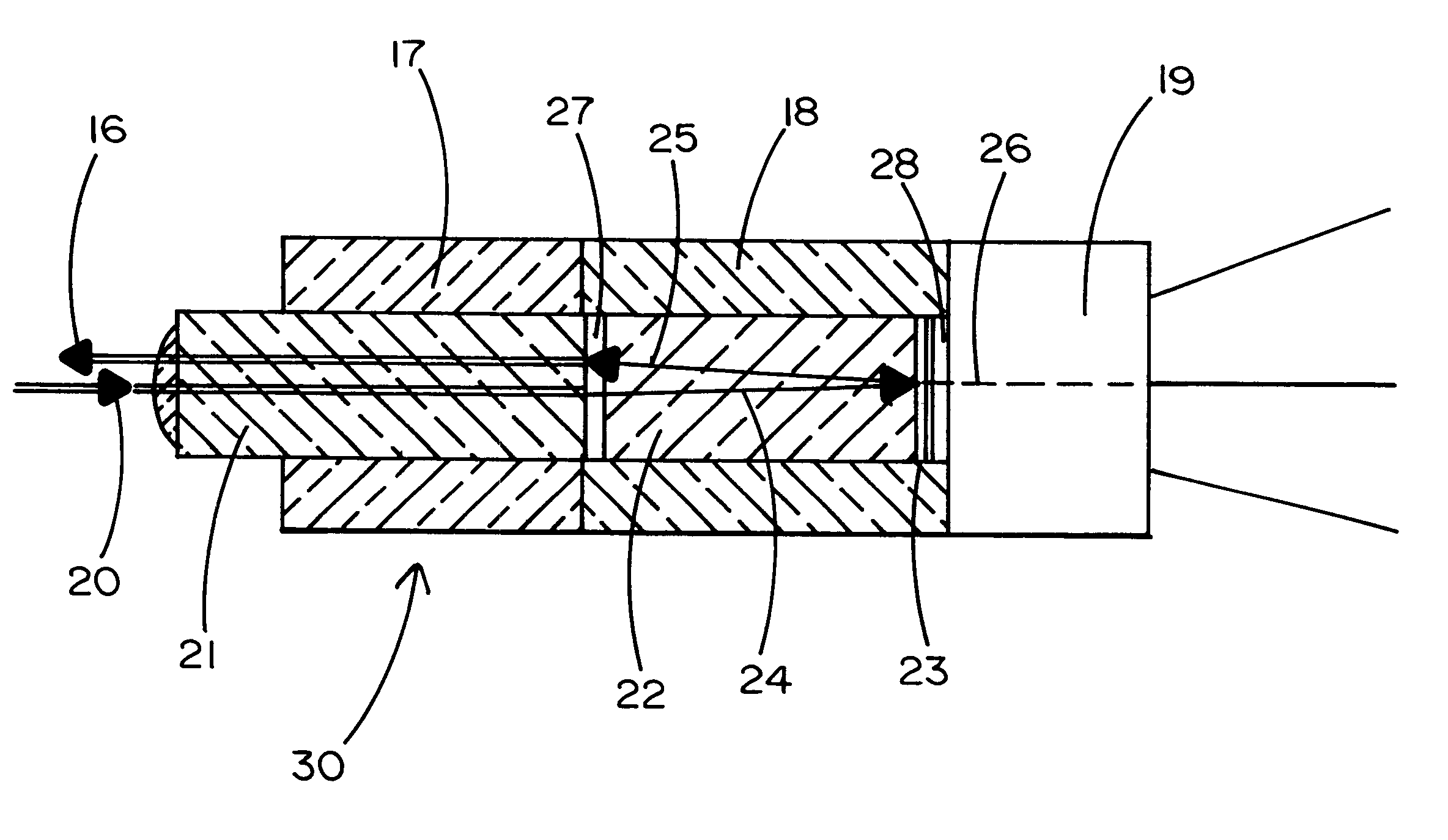
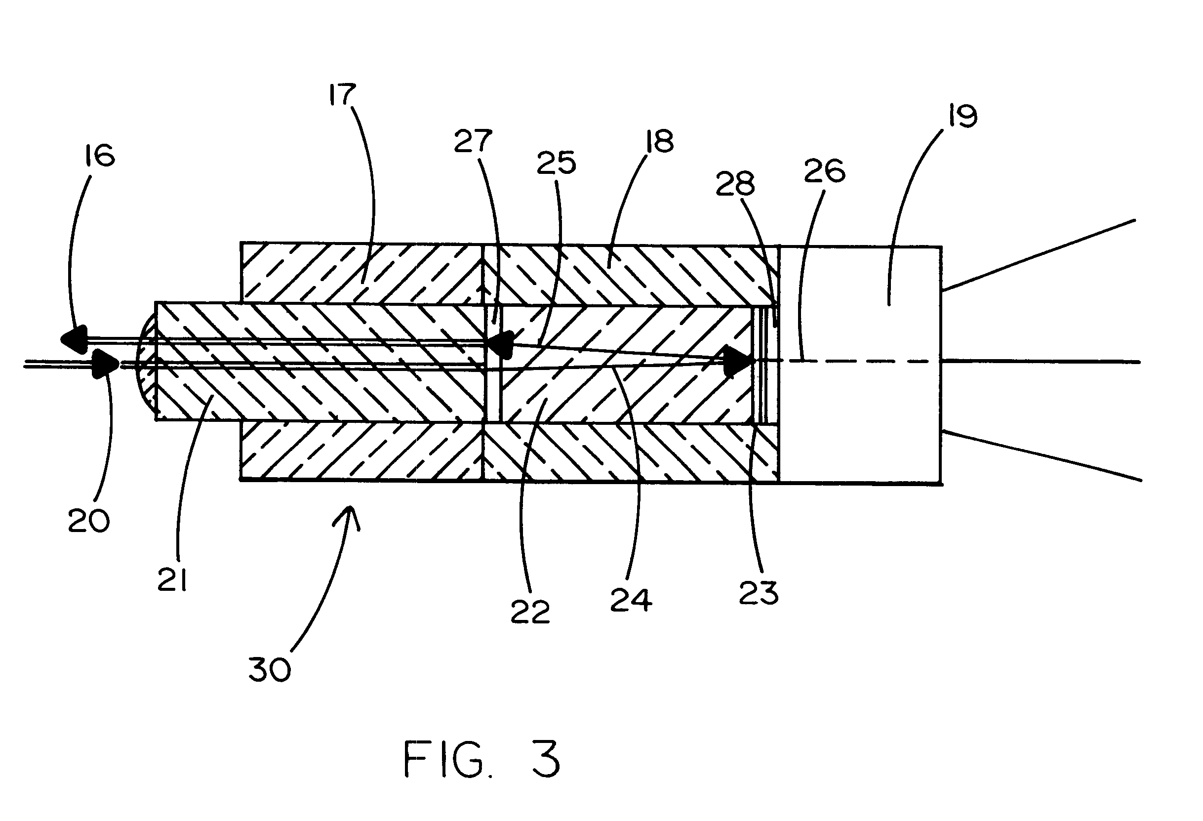
Reference will be made to FIG. 3 which illustrates a preferred embodiment of the present invention. An optical filtering assembly 30 used in the temperature compensated multi-port power-monitoring packages is described. The optical path of the inventive assembly comprises two optical glass fibers (input fiber 20 and reflective fiber 16) inserted into a multi-capillary glass ferrule 21 to provide a fiber-ferrule sub-assembly. Also included in the assembly is a collimating (GRIN or aspheric) lens 22 and a spectral shaping (reflecting) glass filter 23 which is coated directly onto the GRIN lens 22. The lens 22 collimates the light emitted from the input optical fiber 20 into parallel rays, which hit the filter element 23. The filter splits the input collimated light 24 into two beams 26 and 25. The transmitted beam 26 is a product specific percentage typically small (1% or less) of the total optical power. After the transmitted beam 26 passes through the filter element 23, it then ente...


PUM


Abstract

An optical power monitor comprises a fiber and ferrule assembly telescopically embedded in a first glass tube enclosure and a collimating lens telescopically embedded in a second glass tube enclosure. The two glass tube enclosures are bonded together at their respective facing axial ends. The collimating lens is at a first end substantially adjacent the fiber and ferrule assembly. A second end of the lens is coated with a partially transmissive mirror surface for passing a portion of incident light to a photon detector which is bonded to the second glass tube enclosure.

Description

1. Field of the InventionThe present invention relates to optical monitoring packages in general, and more specifically to multi-port tap monitoring devices and to the manufacturing of such devices with adhesive bonding processes.2. Background ArtSingle-port monitoring packages are widely used in local and long distance optical telecommunication networks. These networks comprise various spectral shaping and isolating optical filter assemblies as parts of dense wavelength division multiplexing (DWDM) systems. The need to design reliable monitors for such systems, which are subject to various thermal and mechanical loads during their 20 to 25 year lifetime, is of significant importance. A typical prior art monitoring assembly is shown in FIG. 1 and comprises two optical glass components; a low percentage 1.times.2 tap coupler (3) and a single fiber (5) coupled to a photo detector (6). The tap coupler is spliced into the system (1) and the low percentage leg (5) of the coupler is splic...

Claims


Application Information

Patent Timeline
Patent Type & Authority Patents(United States)
IPC IPC(8): G02B6/42G02B6/38
CPCG02B6/4204G02B6/3845
Inventor QIN, YISHI, ZHOUZHENGFRANCIS, KURT R.
Owner HARBIN NEXFON OPTRONICS
Why Eureka
Try Eureka