
Radiation and melt treated ultra high molecular weight polyethylene prosthetic device and method

Inactive Publication Date: 2003-11-04
CENTPULSE ORTHOPEDICS +1
View PDF25 Cites 397 Cited by
  • Summary
  • Abstract
  • Description
  • Claims
  • Application Information

AI Technical Summary

Benefits of technology

It is an object of the invention to provide an implantable prosthesis device formed at least in part of radiation treated ultra high molecular weight polyethylene (UHMWPE) having no detectable free radicals, so as to reduce production of fine particles from the prosthesis during wear of the prosthesis.
It is another object of the invention to reduce osteolysis and inflammatory reactions resulting from prosthesis implants.
It is yet another object of the invention to provide a prosthesis which can remain implanted within a person for prolonged periods of time.
A still further object of the invention is to provide improved UHMWPE which has improved wear resistance.
The invention also features a method of making a medical prosthesis from UHMWPE having substantially no detectable free radicals, the prosthesis resulting in reduced production of particles from the prosthesis during wear of the prosthesis. Radiation treated UHMWPE having no detectable free radicals is provided. A medical prosthesis is formed from this UHMWPE so as to reduce production of particles from the prosthesis during wear of the prosthesis, the UHMWPE forming a load bearing surface of the prosthesis. Formation of the prosthesis can be accomplished by standard procedures known to those skilled in the art, e.g., machining.
Also provided in this invention is a method of treating a body in need of a medical prosthesis. A shaped prosthesis formed of radiation treated UHMWPE having substantially no detectable free radicals is provided. The prosthesis is applied to the body in need of the prosthesis. The prosthesis reduces production of particles from the prosthesis during wear of the prosthesis. In preferred embodiments, the UHMWPE forms a load bearing surface of the prosthesis.

Problems solved by technology

Wear of the synthetic polymer against the metal of the articulation, however, can result in severe adverse effects which predominantly manifest after several years.
The macrophage, often being unable to digest these polyethylene particles, synthesize and release large numbers of cytokines and growth factors which can ultimately result in bone resorption by osteoclasts and monocytes.
This osteolysis can contribute to mechanical loosening of the prosthesis components, thereby sometimes requiring revision surgery with its concomitant problems.

Method used


Image

  • Radiation and melt treated ultra high molecular weight polyethylene prosthetic device and method
  • Radiation and melt treated ultra high molecular weight polyethylene prosthetic device and method
  • Radiation and melt treated ultra high molecular weight polyethylene prosthetic device and method

Examples


example 1

Method of Making Melt-Irradiated UHMWPE (MIR)

This example illustrates electron irradiation of melted UHMWPE.

A cuboidal specimen of size 10 mm.times.12 mm.times.60 mm, prepared from conventional ram extruded UHMWPE bar stock (GUR 415, obtained from Westlake Plastics, Lenni, Pa.) was placed in a chamber. The atmosphere within the chamber consisted of low oxygen nitrogen gas (<0.5 ppm oxygen gas) (obtained from AIRCO, Murray Hill, N.J.). The pressure in the chamber was approximately 1 atm. The temperature of the sample and the irradiation chamber was controlled using a heater, a variac and a thermocouple readout (manual) or temperature controller (automatic). The chamber was heated with a 270 W heating mantle. The chamber was heated (controlled by the variac) at a rate such that the steady state temperature of the sample was about 175.degree. C. The sample was held at the steady state temperature for 30 minutes before starting the irradiation.

Irradiation was done using a van de Graaff ...

example 2

Comparison of Properties of GUR 415 UHMWPE Bar Stock and Melt-Irradiated (MIR) GUR 415 UHMWPE Bar Stock (20 MRad)

This example illustrates various properties of the irradiated and unirradiated samples of UHMWPE bar stock (GUR 415) obtained from Example 1. The tested samples were as follows: the test sample was bar stock which was molten and then irradiated while molten; control was bar stock (no heating / melting, no irradiation).

(A) Differential Scanning Calorimetry (DSC)

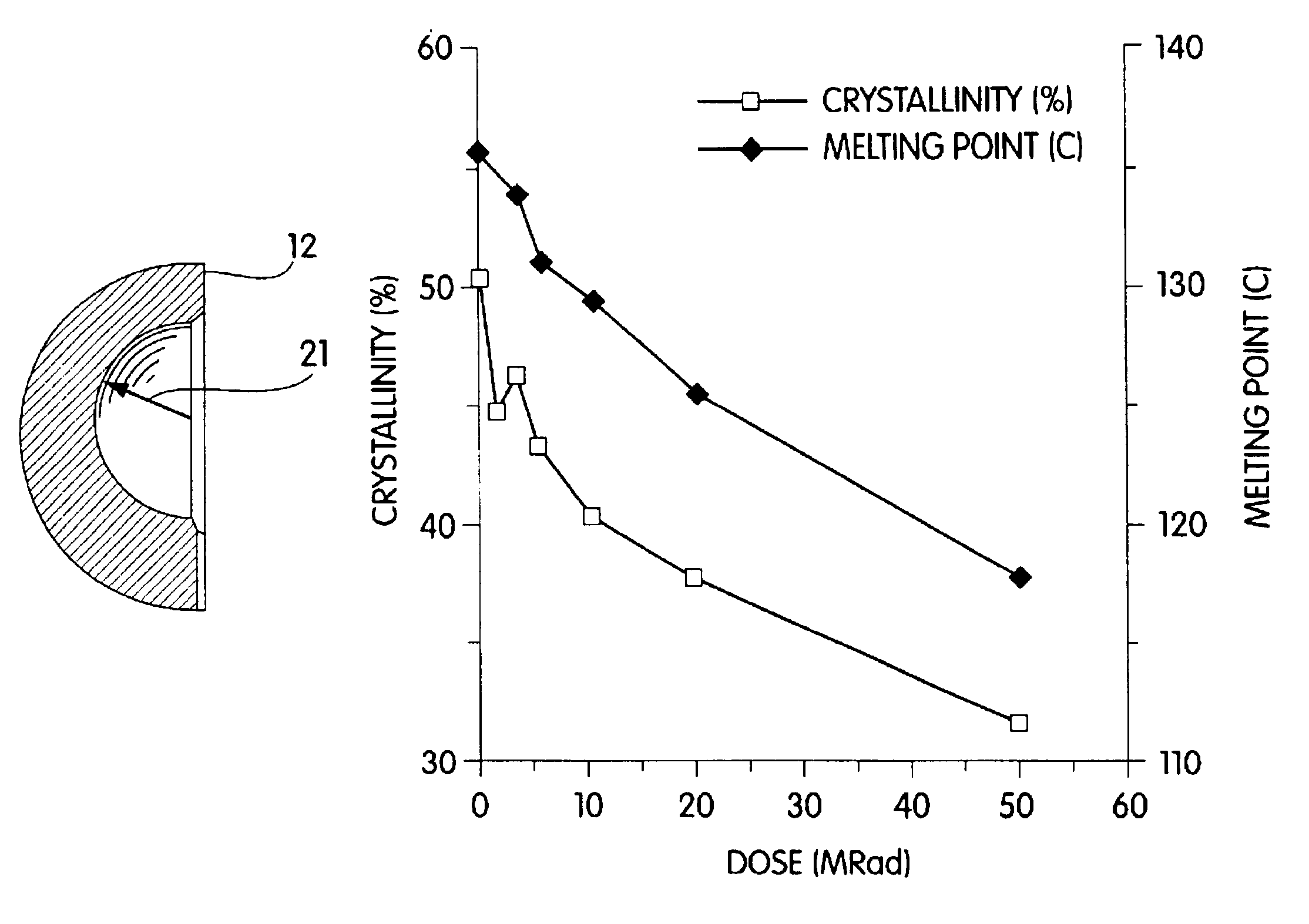
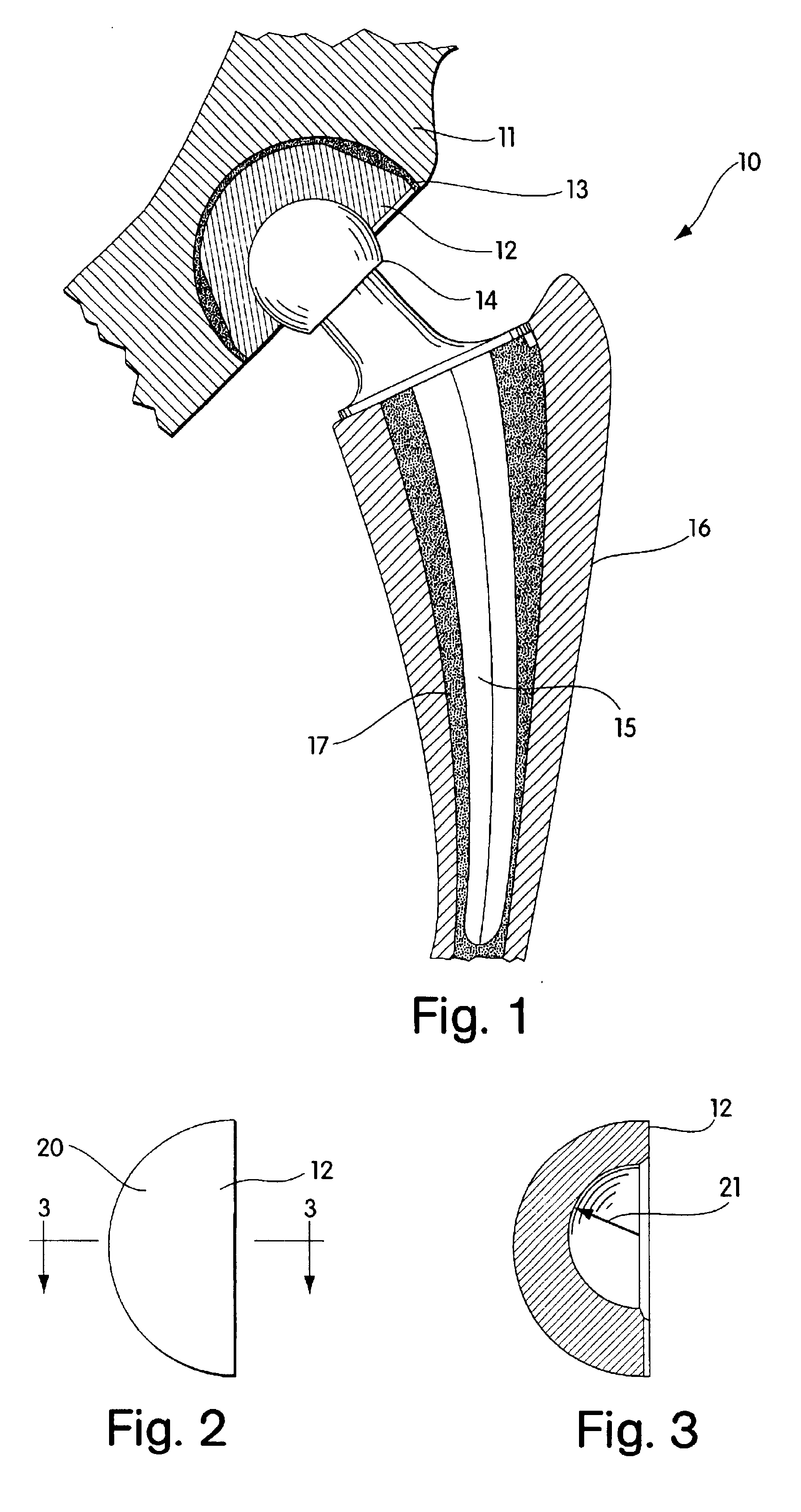
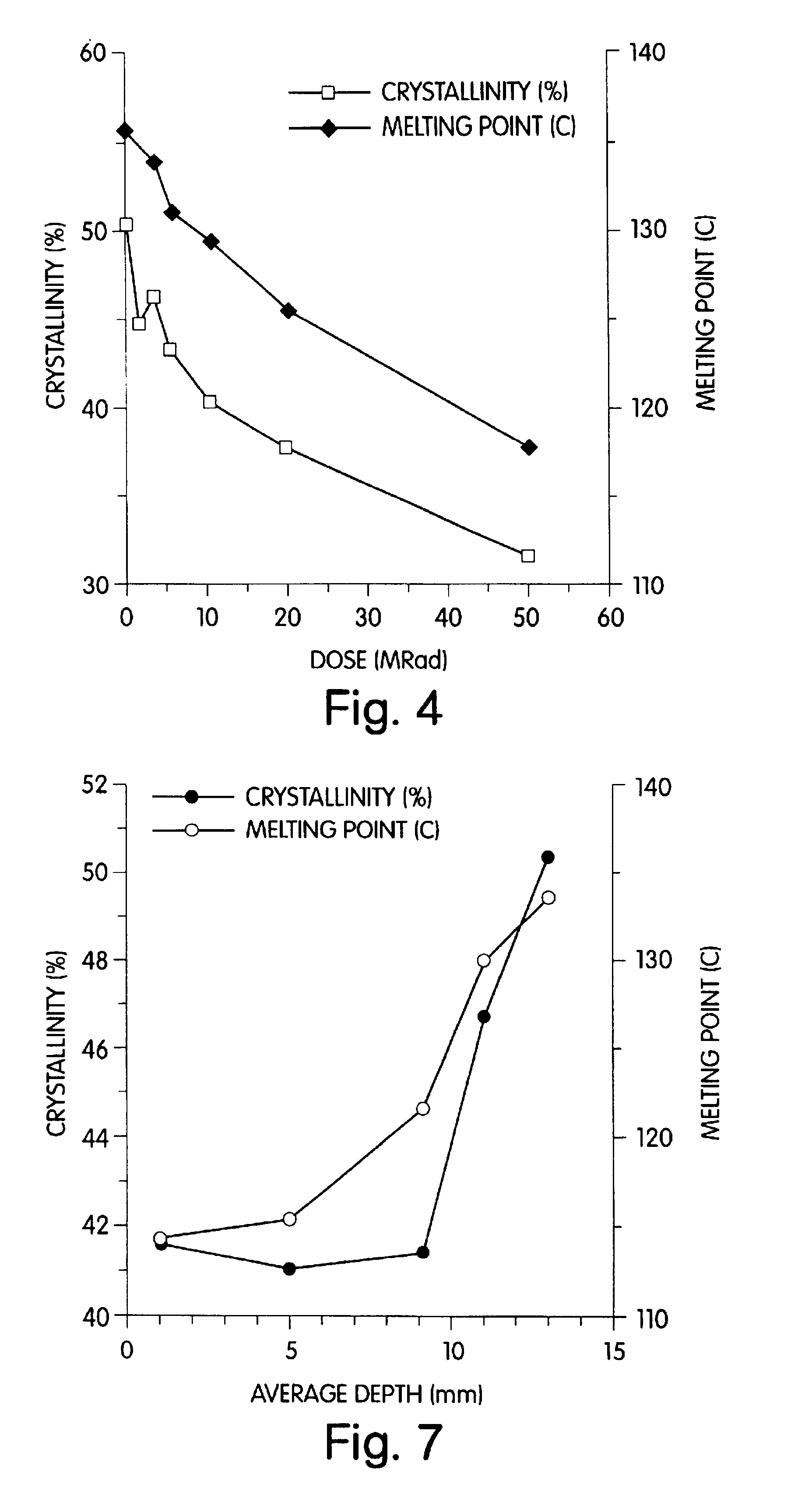
A Perkin-Elmer DSC7 was used with an ice-water heat sink and a heating and cooling rate of 10.degree. C. / minute with a continuous nitrogen purge. The crystallinity of the samples obtained from Example 1 was calculated from the weight of the sample and the heat of melting of polyethylene crystals (69.2 cal / g). The temperature corresponding to the peak of the endotherm was taken as the melting point. The lamellar thickness was calculated by assuming a lamellar crystalline morphology, and knowing the heat of crystallizat...

example 3

Method of Making Melt-Irradiated (MIR) UHMWPE Conventional Articular Cups

This example illustrates electron irradiation of a melted UHMWPE conventional articular cup.

A conventional articular cup (high conformity unsterilized UHMWPE cup made by Zimmer, Inc., Warsaw, Ind.) of internal diameter 26 mm and made of GUR 415 ram extruded bar stock, was irradiated under controlled atmosphere and temperature conditions in an air-tight chamber with a titanium cup holder at the base and a thin stainless steel foil (0.001 inches thick) at the top. The atmosphere within this chamber consisted of low oxygen nitrogen gas (<0.5 ppm oxygen gas) (obtained from AIRCO, Murray Hill, N.H.). The pressure in the chamber was approximately 1 atm. The chamber was heated using a 270 W heating mantle at the base of the chamber which was controlled using a temperature controller and a variac. The chamber was heated such that the temperature at the top surface of the cup rose at approximately 1.5.degree. to 2.degre...


PUM

PropertyMeasurementUnit
Timeaaaaaaaaaa
Angleaaaaaaaaaa
Angleaaaaaaaaaa

Abstract

A medical prosthesis for use within the body which is formed of radiation treated ultra high molecular weight polyethylene having substantially no detectable free radicals, is described. Preferred prostheses exhibit reduced production of particles from the prosthesis during wear of the prosthesis, and are substantially oxidation resistant. Methods of manufacture of such devices and material used therein are also provided.

Description

FIELD OF THE INVENTIONThe present invention relates to the orthopedic field and the provision of prostheses, such as hip and knee implants, as well as methods of manufacture of such devices and material used therein.BACKGROUND OF THE INVENTIONThe use of synthetic polymers, e.g., ultra high molecular weight polyethylene, with metallic alloys has revolutionized the field of prosthetic implants, e.g., their use in total joint replacements for the hip or knee. Wear of the synthetic polymer against the metal of the articulation, however, can result in severe adverse effects which predominantly manifest after several years. Various studies have concluded that such wear can lead to the liberation of ultrafine particles of polyethylene into the periprosthetic tissues. It has been suggested that the abrasion stretches the chain folded crystallites to form anisotropic fibrillar structures at the articulating surface. The stretched-out fibrils can then rupture, leading to production of submicr...

Claims


Application Information

Patent Timeline
IPC IPC(8): A61F2/32A61F2/46A61L27/16A61L27/00A61F2/30A61F2/00A61F2/34A61F2/36B29C35/08B29C43/16B29C43/00C08F110/02C08F110/00A61F2/38C08F10/02C08J3/24C08J3/28C08J7/00C08L23/04C08L23/06
CPCA61F2/32A61F2/4657A61L27/16C08L23/06A61F2/30767A61F2/3094C08F110/02B29L2031/7532B29K2995/0089B29K2995/0087A61F2/34A61F2/36A61F2/3662A61F2002/30065A61F2002/30084A61F2002/30125A61F2002/30158A61F2002/30324A61F2002/30616A61F2002/30685A61F2002/30934A61F2002/3233A61F2002/3464A61F2002/3493A61F2002/3495A61F2002/3611A61F2002/3623A61F2002/3625A61F2002/3631A61F2002/365A61F2002/4631A61F2002/4666A61F2210/0071A61F2230/0008A61F2230/0026A61F2250/0036A61F2310/00011A61F2310/00017A61F2310/00023A61F2310/00029A61F2310/00071A61F2310/00179A61L2430/24B29C43/00B29C43/16B29C2035/085C08F2500/01C08F2500/14A61F2/468Y10T428/31692Y10T428/31855A61F2002/3462A61F2002/349B29C2035/0877B29C71/02B29C71/04B29K2023/0683
Inventor MERRILL, EDWARD W.HARRIS, WILLIAM H.JASTY, MURALIMURATOGLU, ORHUNBRAGDON, CHARLES R.O'CONNOR, DANIEL O.VENUGOPALAN, PREMNATH
Owner CENTPULSE ORTHOPEDICS
Learn More