
Production of olefins

a technology of olefins and olefins, which is applied in the field of olefin production, can solve the problems of low yield, unstable conversion against time, and low stability of crystalline silicate catalysts

Inactive Publication Date: 2003-11-11
FINA RES SA
View PDF6 Cites 44 Cited by
  • Summary
  • Abstract
  • Description
  • Claims
  • Application Information

AI Technical Summary

Benefits of technology

It is another object of the invention to provide a process for producing propylene having a high propylene yield and purity.
It is a further object of the present invention to provide such a process which can produce olefin effluents which are within, at least, a chemical grade quality.
It is yet a further object of the present invention to provide a process for producing olefins having a stable olefinic conversion and a stable product distribution over time.

Problems solved by technology

It is further known that when crystalline silicates are employed as catalysts for the conversion of paraffins into olefins, such conversion is not stable against time.
However, when it is desired to produce propylene, not only are the yields low but also the stability of the crystalline silicate catalyst is low.
Not only is this increase in yield quite small, but also the ZSM-5 catalyst has low stability in the FCC unit.
Traditional methods to increase propylene production are not entirely satisfactory.
For example, additional naphtha steam cracking units which produce about twice as much ethylene as propylene are an expensive way to yield propylene since the feedstock is valuable and the capital investment is very high.
Propane dehydrogenation gives a high yield of propylene but the feedstock (propane) is only cost effective during limited periods of the year, making the process expensive and limiting the production of propylene.
Propylene is obtained from FCC units but at a relatively low yield and increasing the yield has proven to be expensive and limited.
Often, combined with a steam cracker, this technology is expensive since it uses ethylene as a feedstock which is at least as valuable as propylene.
This specification only exemplifies olefin conversion processes over short periods (e.g. a few hours) and does not address the problem of ensuring that the catalyst is stable over longer periods (e.g. at least 160 hours or a few days) which are required in commercial production.
Moreover, the requirement for high space velocities is undesirable for commercial implementation of the olefin conversion process.
Although in the steaming step aluminum atoms are chemically removed from the crystalline silicate framework structure to form alumina particles, those particles cause partial obstruction of the pores or channels in the framework.
If the binder which is used in conjunction with the crystalline silicate is itself catalytically active, this may alter the conversion and / or the selectivity of the catalyst.
The presence of aluminum in the binder would tend to reduce the olefin selectivity of the catalyst, and to reduce the stability of the catalyst over time.
This can greatly decrease the yield on an olefin basis of the catalyst to produce the desired olefin, for example propylene, with increasing time on stream.
When such nickel-based catalysts are used with a C.sub.4 cut, a significant conversion of the mono-olefins into paraffins by hydrogenation cannot be avoided.
The present inventors have found that the use of a low olefin partial pressure, for example atmospheric pressure, tends to lower the incidence of hydrogen transfer reactions in the cracking process, which in turn reduces the potential for coke formation which tends to reduce catalyst stability.

Method used


Image

  • Production of olefins
  • Production of olefins
  • Production of olefins

Examples


example 2

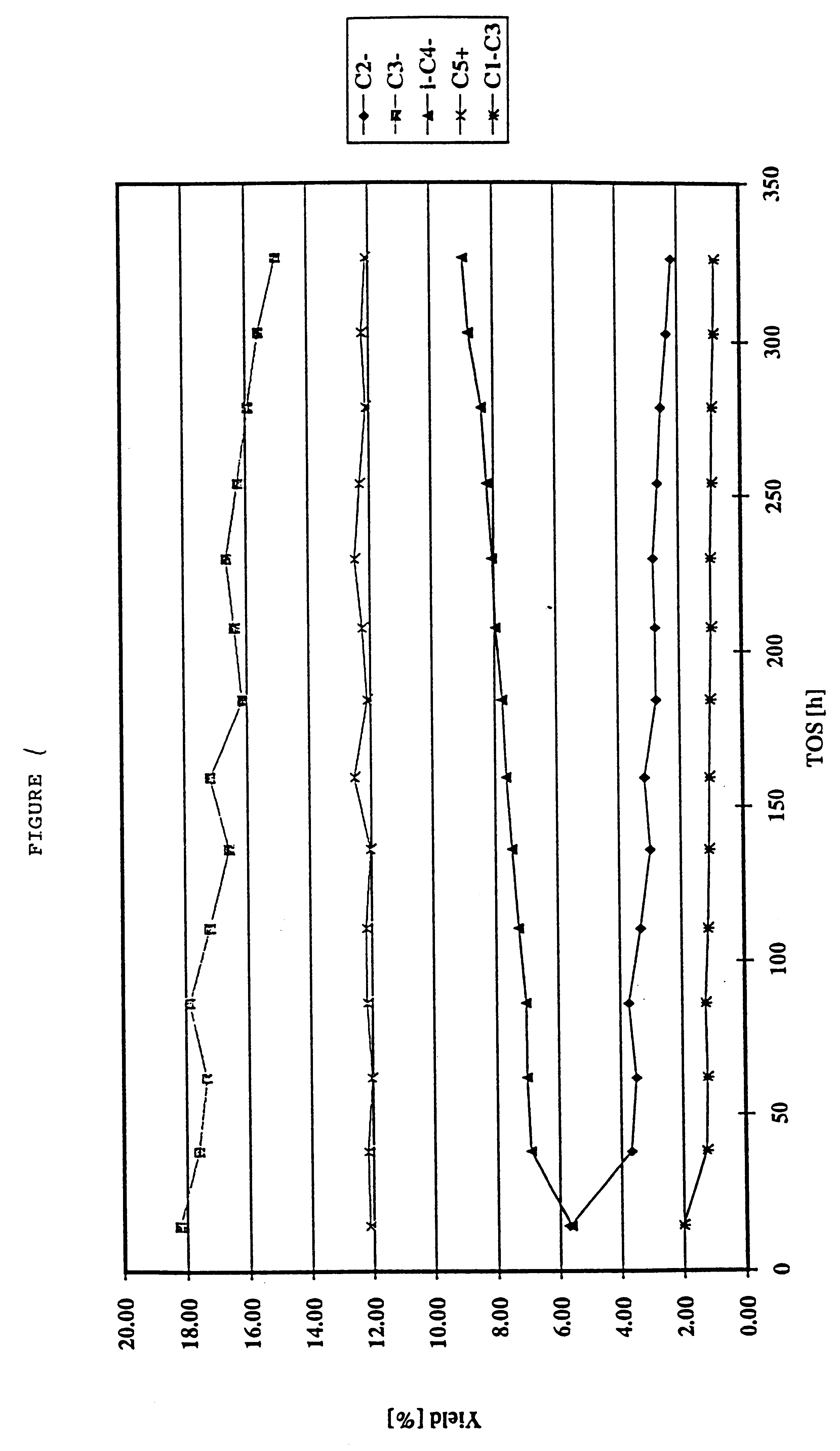
Example 1 was repeated but using a different feedstock comprising, rather than a light cracked naphtha, a fractionated C.sub.5 cut from a light cracked naphtha. In addition, in the catalytic cracking process the inlet temperature was 548.degree. C. The hydrocarbon outlet pressure was around 1 bar (i.e. atmospheric pressure).

Table 4 shows the distribution of the hydrocarbon species in the feed of the C.sub.5 cut from the LCN, in the hydrotreated feed which had been subjected to a diene hydrogenation process as in Example 1, and in the effluent after the cracking process. It may be seen that the feed substantially initially comprises C.sub.5 species and that following the catalytic cracking process, the olefin content has remained substantially the same but the amount of C.sub.5 species in the effluent is significantly decreased as compared to the amount of such species in the initial feedstock. Again, the C.sub.2 to C.sub.4 lighter olefins may readily be fractionated from the effluen...

example 3

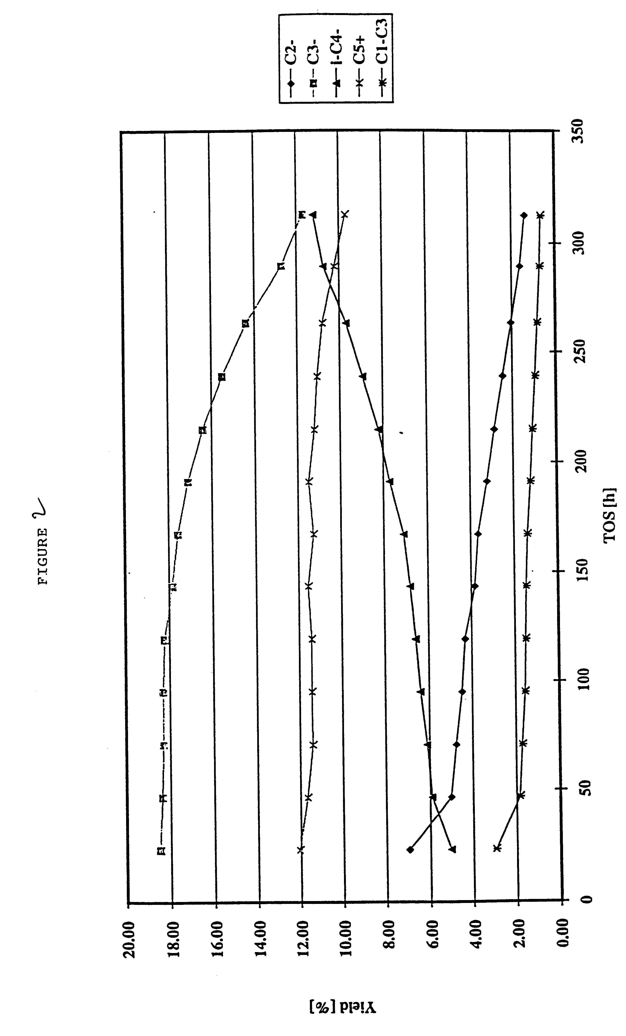
Example 1 was repeated but using as the feedstock, instead of a light cracked naphtha, a C.sub.4 raffinate (raffinate II) from an MTBE unit in a refinery. In addition, the inlet temperature of the feedstock was around 560.degree. C. The hydrocarbon outlet pressure was around 1 bar (atmospheric pressure).

It may be seen from Tables 7 to 9 that C.sub.2 and primarily C.sub.3 olefins are produced from the C.sub.4 olefinic feedstock in accordance with the invention. In the effluent, around 34.5% of the olefin content is present as C.sub.2 and / or C.sub.3 olefins. The C.sub.2 and / or C.sub.3 olefins may be readily be fractionated from the effluent. The propylene yield on an olefin basis was 29%.

example 4

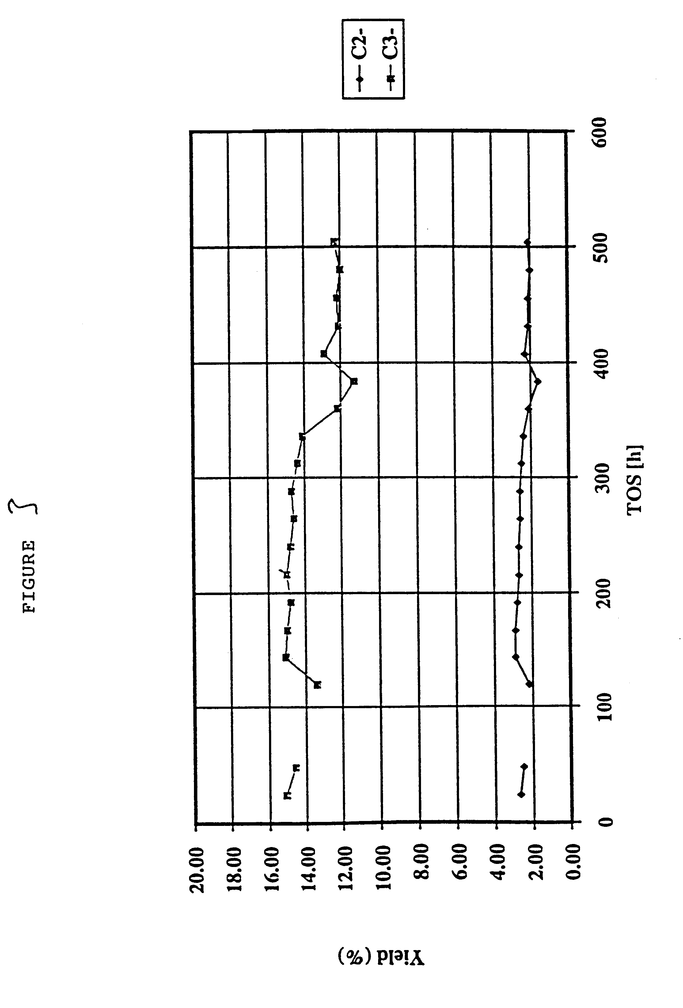
This example illustrates the catalytic cracking of an olefin feedstock comprising 1-hexene over silicalite which has been subjected to a steaming and de-alumination process and calcination, with the catalytic cracking process being performed at a variety of inlet temperatures for the feed into the reactor tube.

The silicalite catalyst comprised a silicalite having a silicon / aluminum ratio of around 120, and having a crystallite size of from 4 to 6 microns and a surface area (BET) of 399 m.sup.2 / g. The silicalite was pressed, washed and the 35-45 mesh fraction was retained. The silicalite was subjected to a steaming process in an atmosphere of 72 vol % stream and 28 vol % nitrogen at a temperature of 550.degree. C. at atmospheric pressure for a period of 48 hours. Then 11 g of the steamed silicalite was treated with an EDTA solution (100 ml containing 0.0225M of Na.sub.2 EDTA) thereby to de-aluminate the silicalite under reflux for a period of 6 hours. The slurry was then washed thor...


PUM


Abstract

A process for the catalytic cracking of an olefin-containing feedstock which is selective towards light olefins in the effluent, the process comprising contacting a hydrocarbon feedstock containing at least one olefin with a MFI-type crystalline silicate catalyst having a silicon / aluminum atomic ratio of at least about 180, which has been obtained by pretreating so as to increase the silicon / aluminum atomic ratio thereof by heating the catalyst in steam and de-aluminating the catalyst by treating the catalyst with a complexing agent for aluminum, at an inlet temperature of from 500 to 600° C. and at an olefin partial pressure of from 0.1 to 2 bars to produce an effluent with an olefin content of lower molecular weight than that of the feedstock.

Description

BACKGROUND TO THE INVENTIONThe present invention relates to a process for cracking an olefin-rich hydrocarbon feedstock which is selective towards light olefins in the effluent. In particular, olefinic feedstocks from refineries or petrochemical plants can be converted selectively so as to redistribute the olefin content of the feedstock in the resultant effluent.DESCRIPTION OF THE PRIOR ARTIt is known in the art to use zeolites to convert long chain paraffins into lighter products, for example in the catalytic dewaxing of petroleum feedstocks. While it is not the objective of dewaxing, at least parts of the paraffinic hydrocarbons are converted into olefins. It is known in such processes to use crystalline silicates for example of the MFI type, the three-letter designation "MFI" representing a particular crystalline silicate structure type as established by the Structure Commission of the International Zeolite Association. Examples of a crystalline silicate of the MFI type are the ...

Claims


Application Information

Patent Timeline
IPC IPC(8): C10G11/05C10G11/00B01J29/40B01J29/035
CPCC10G11/05C10G2400/20
Inventor DATH, JEAN-PIERREDELORME, LUCGROOTJANS, JACQUES-FRAN.CEDILLA.OISVANHAEREN, XAVIERVERMEIREN, WALTER
Owner FINA RES SA
Features
  • Generate Ideas
  • Intellectual Property
  • Life Sciences
  • Materials
  • Tech Scout
  • Unparalleled Data Quality
  • Higher Quality Content
  • 60% Fewer Hallucinations
Learn More