
Fluorescent color conversion film, fluorescent color conversion filter using the conversion film, and organic light-emitting device equipped with the conversion filter

a conversion filter and fluorescent technology, applied in the direction of discharge tube luminescnet screen, discharge tube/lamp details, incadescent envelope/vessel, etc., can solve the problems of chromaticity gradually deviating, difficult technology for arrangement, and high cost of manufacturing such an arrangement, so as to reduce the monomer in the system, prevent the dielectric constant of the matrix resin, and improve the color conversion characteristic

Inactive Publication Date: 2003-11-25
SHARP KK
View PDF23 Cites 56 Cited by
  • Summary
  • Abstract
  • Description
  • Claims
  • Application Information

AI Technical Summary

Benefits of technology

It is a further object of the present invention to provide a fluorescent color conversion film formed by a photolithography process that suppresses degradation in color conversion characteristic by compensating for decrease in dielectric constant due to solidification of the system.
In the above structure, at least one of the anode and cathode is favorably transparent to the wavelength range of the light emitted from the organic light-emitting element, which radiates light through the transparent electrode into the fluorescent color conversion film. It is known in the art that obtaining a transparent anode is easier. A transparent anode is preferably employed also in the present invention.

Problems solved by technology

The technology for the arrangement is difficult and the manufacture of such an arrangement is costly.
In addition, the method has a problem that chromaticity gradually deviates because the lifetimes of the three light-emitting materials differ from each other.
However, an organic white-light-emitting device exhibiting a long life and high brightness that are necessary to attain red, green and blue light of high brightness has not yet been obtained.
In forming a fluorescent color conversion film using organic fluorescent dye dispersed in a liquid photoresist by means of photolithography process, there has been a problem that proportion of monomer decreases by polymerization due to optical or thermal curing of the resist.
As a result, the dielectric constant of the system decreases, causing deterioration of color conversion characteristics (fluorescence quantum yield, in particular) of the fluorescent color conversion film.

Method used


Image

  • Fluorescent color conversion film, fluorescent color conversion filter using the conversion film, and organic light-emitting device equipped with the conversion filter
  • Fluorescent color conversion film, fluorescent color conversion filter using the conversion film, and organic light-emitting device equipped with the conversion filter
  • Fluorescent color conversion film, fluorescent color conversion filter using the conversion film, and organic light-emitting device equipped with the conversion filter

Examples


example 1

The filter portion illustrated in FIG. 1 is fabricated by the process described below.

Fabrication of Color Filter Layers

A transparent substrate 5 of corning glass (143.times.112.times.1.1 mm) was prepared. Color filter red (available under the trade name Colormosaic CR-7001 from Fuji Film Olin Co., Ltd.) was coated by means of spin-coating on the substrate, followed by patterning by photolithography, to obtain a red filter layer having a stripe pattern of 1 .mu.m thickness, 0.104 mm width and 0.226 mm gap.

Similarly, each of color filter blue (available under the trade name Colormosaic CB-7001 from Fuji Film Olin Co., Ltd.) and color filter green (available under the trade name Colormosaic CG-7001 from Fuji Film Olin Co., Ltd.) was coated by means of spin-coating on the substrate, followed by patterning by photolithography, to obtain each of a blue filter layer 4 and a green filter layer 3 each having a stripe pattern of 1 .mu.m thickness, 0.104 mm width and 0.226 mm gap.

Fabrication ...

example 2

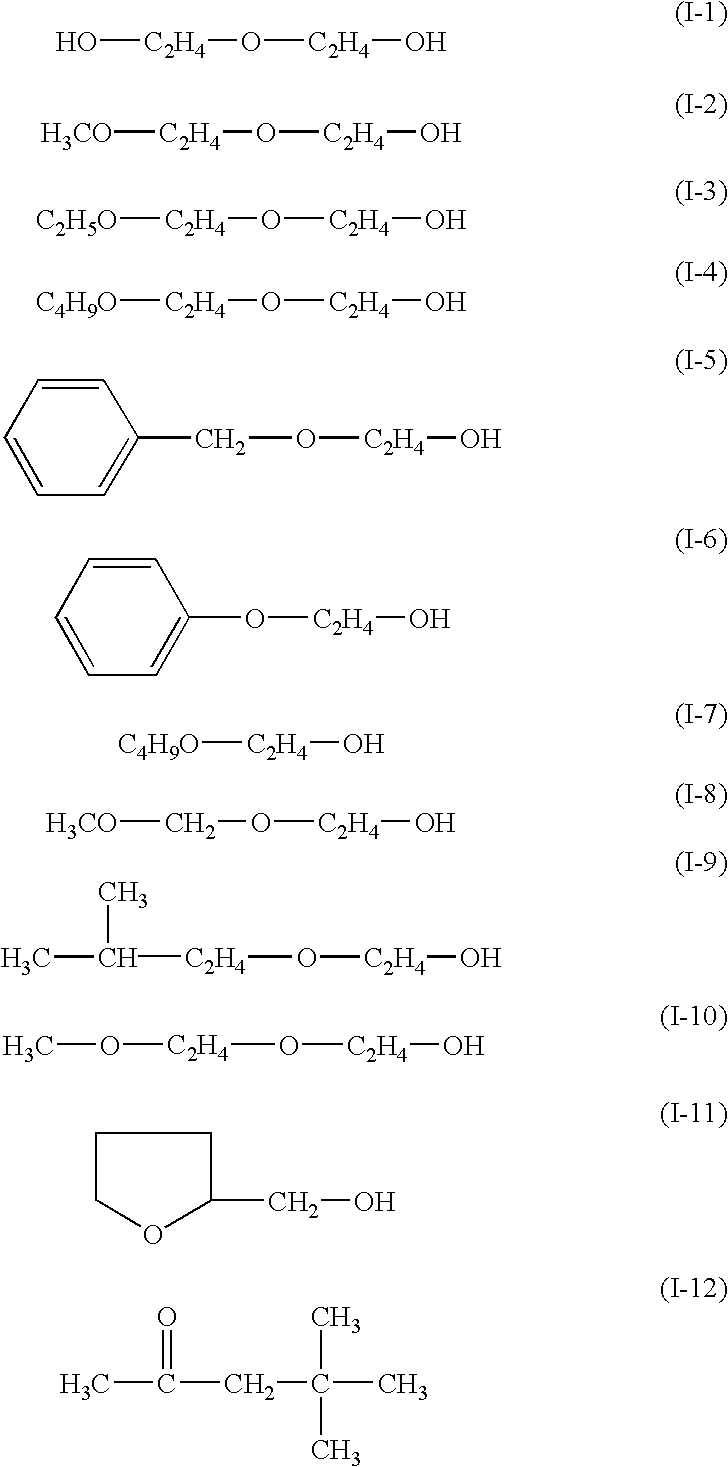
A fluorescent color conversion filter of Example 2 was fabricated repeating the same process as in Example 1 except that 10 parts by weight of diethylene glycol of Formula (I-1) of Example 1 was replaced by 10 parts by weight of diethylene glycol monomethyl ether of Formula (I-2), and an organic light-emitting device of Example 2 equipped with thus fabricated fluorescent color conversion filter was fabricated.

Example 3

A fluorescent color conversion filter of Example 3 was fabricated repeating the same process as in Example 1 except that 10 parts by weight of diethylene glycol of Formula (I-1) of Example 1 was replaced by 10 parts by weight of diethylene glycol monoethyl ether of Formula (I-3), and an organic light-emitting device of Example 3 equipped with thus fabricated fluorescent color conversion filter was fabricated.

example 4

A fluorescent color conversion filter of Example 4 was fabricated repeating the same process as in Example 1 except that 10 parts by weight of diethylene glycol of Formula (I-1) of Example 1 was replaced by 10 parts by weight of 2-benzyloxyethanol of Formula (I-5), and an organic light-emitting device of Example 4 equipped with thus fabricated fluorescent color conversion filter was fabricated.


PUM


Abstract

A high boiling-point solvent, included in a fluorescent color conversion film, suppresses degradation in color conversion characteristic by compensating for a decrease in dielectric constant due to solidification of the matrix system. The fluorescent color conversion film of the present invention includes, in addition to the high boiling point solvent, organic fluorescent dyes, which absorb light in a near ultraviolet to visible light region and emit visible light of a different wavelength, and a matrix resin bearing the organic fluorescent dye. The high boiling point solvent has a boiling point of 150° C. or higher and a vapor pressure of 5 mmHg or lower at the temperature of 20° C. The fluorescent color conversion film is useful in a fluorescent color conversion filter, which itself is useful in light-emitting devices, such as self-emitting multi-colored- or full colored-displays, display panels and backlights.

Description

The present invention relates to a fluorescent color conversion film that converts light emitted in near ultraviolet to visible region by a light-emitting element to light with different wavelength in the visible region. The invention also relates to a fluorescent color conversion filter employing such a fluorescent color conversion film. The invention further relates to an organic light-emitting device equipped with such a fluorescent color conversion filter. The fluorescent color conversion filter and the organic light-emitting device are suitably applied to both consumer-oriented and industry-used display apparatuses, such as a self-emitting multi-colored- or full colored-display, a display panel and a backlight.With increasing demand for a flat panel display to replace a conventional CRT, development and practical application of various display devices are being actively conducted. An electroluminescent device (hereinafter referred to as a light-emitting device) is one of the de...

Claims


Application Information

Patent Timeline
Patent Type & Authority Patents(United States)
IPC IPC(8): H01L27/32H01L27/28H01L51/50H01L51/05H01L51/30H05B33/12H05B33/14H05B33/22H10K99/00
CPCH01L27/322H01L51/5036H01L51/005H01L51/0078H01L51/0081H01L51/0059H10K59/38H10K85/60H10K85/631H10K85/311H10K85/324H10K50/125
Inventor TOMIUCHI, YOSHIMASASHIRAISHI, YOTARO
Owner SHARP KK
Learn More