Pulsed laser linescanner for a backscatter absorption gas imaging system

a gas imaging and laser liner technology, applied in optics, instruments, material analysis, etc., can solve the problems of not achieving the additional sensitivity provided by differential imaging, adversely affecting the way, and useful for single-wavelength imaging

Inactive Publication Date: 2004-02-10
SANDIA NAT LAB
View PDF6 Cites 91 Cited by
  • Summary
  • Abstract
  • Description
  • Claims
  • Application Information

AI Technical Summary

Benefits of technology

It is another object of the invention to provide a pulsed linescanned imager that by concentrating the transmitted light in a small number of rows achieves a higher backscattered signal from a given target using a given laser pulse energy and repetition rate than can be obtained by a system employing full-field illumination.
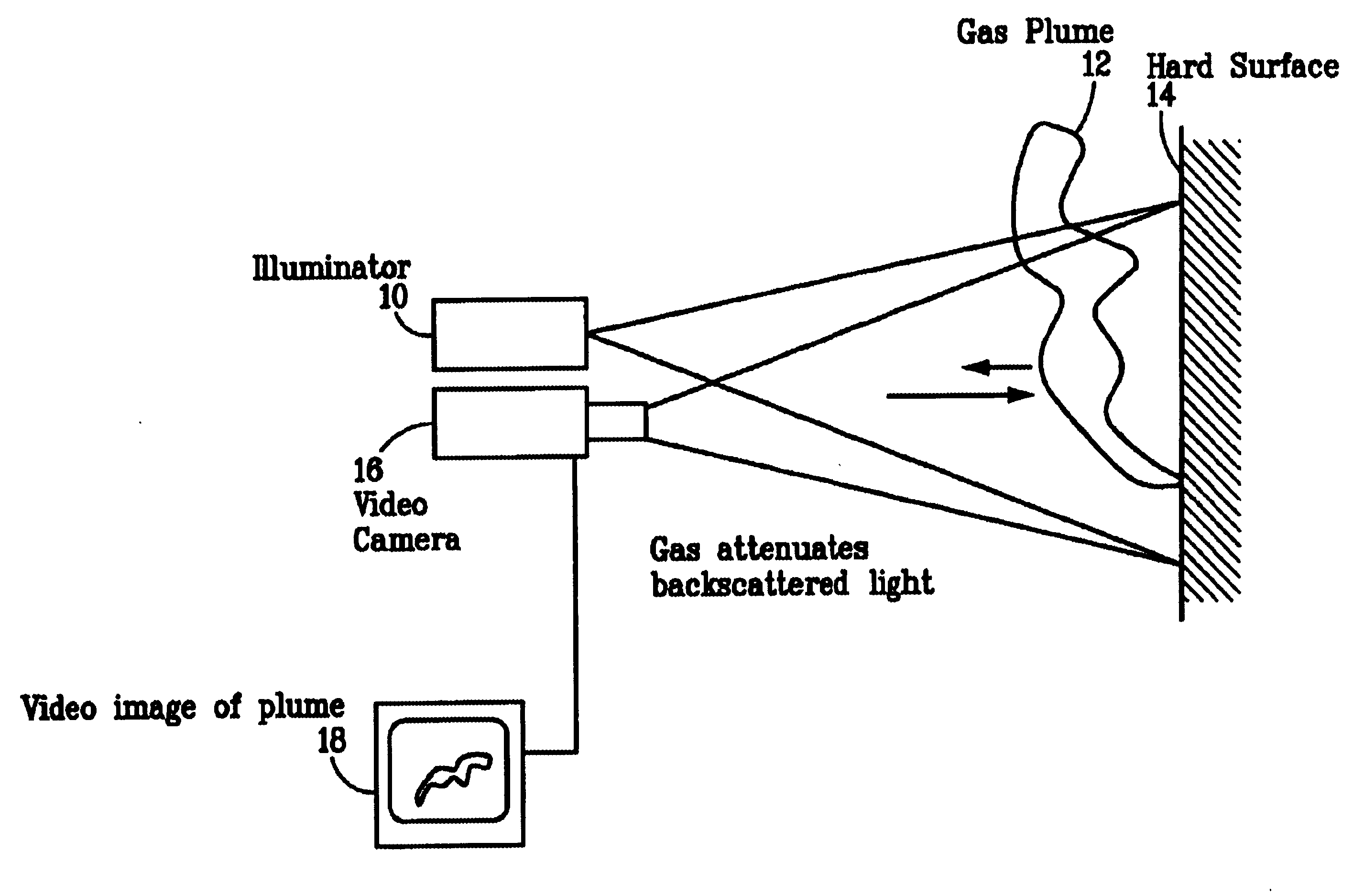
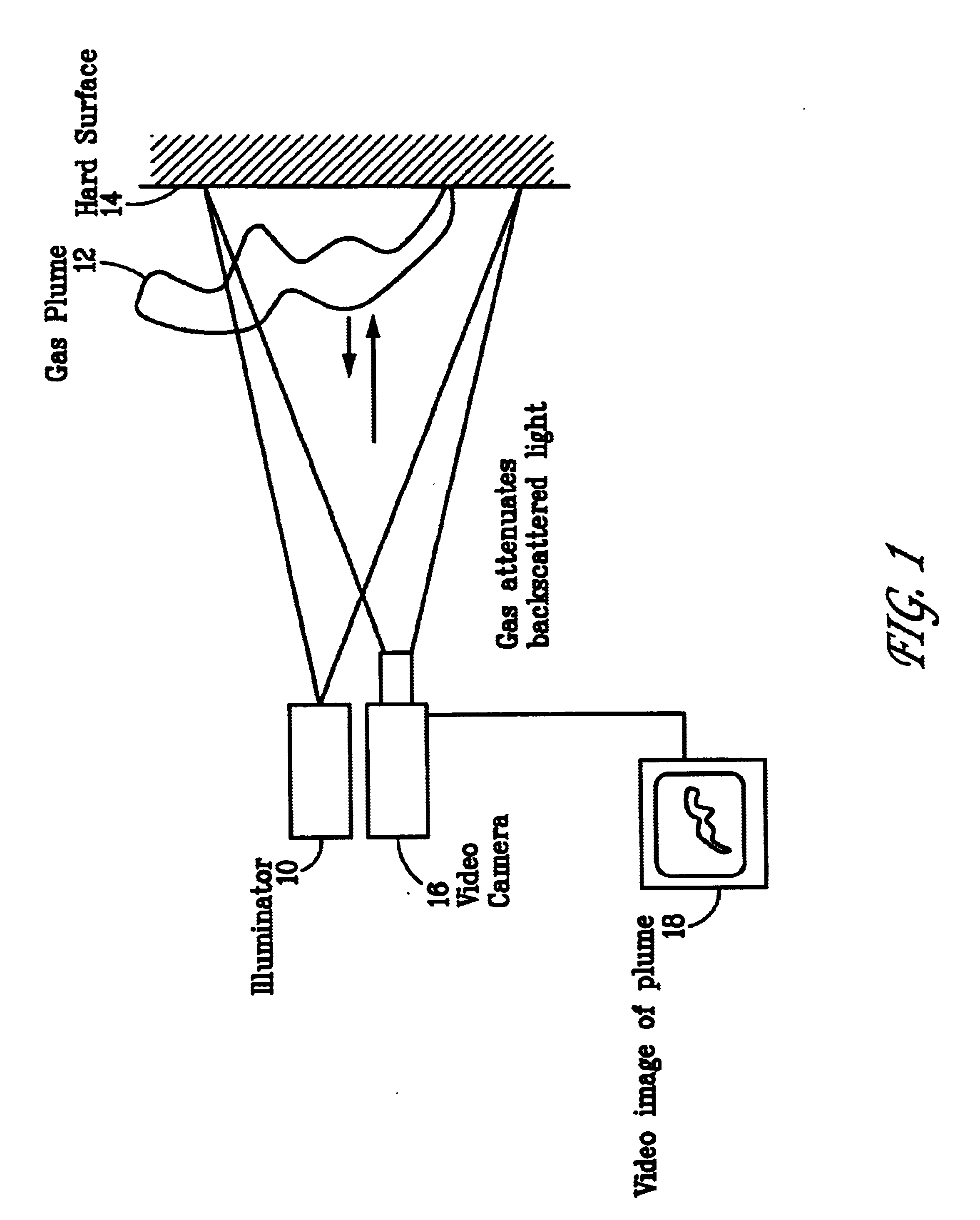
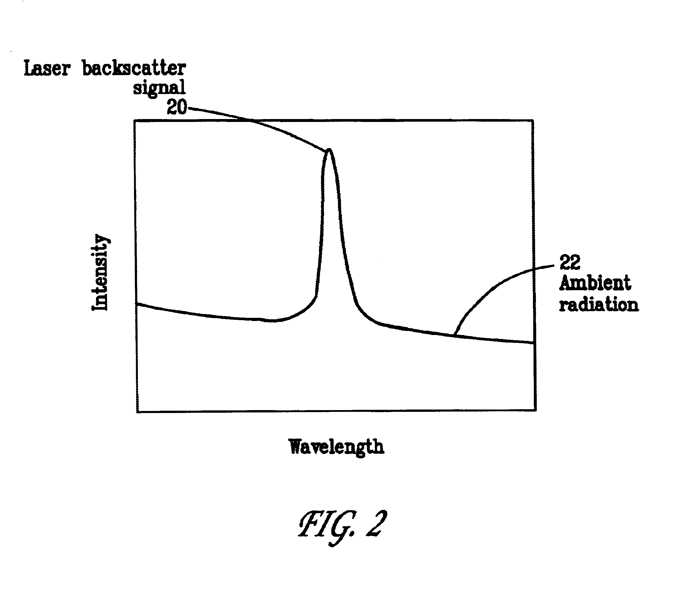
The present invention is an active (laser illuminated) imaging system that is suitable for use as a BAGI imager. As in all BAGI systems, the present invention employs a laser, tuned to a wavelength absorbed by the gas to be detected, that is coupled to a suitable video camera. The laser illuminates the scene as the camera images it. Gases present in the imaged scene are visualized when they absorb the laser light, thus creating a dark region in the video picture. This allows the imager to be used to rapidly detect and pinpoint leaks of gases (such as hydrocarbons found in leaks at petroleum refineries or in natural gas pipelines) that absorb light produced by the laser employed. To maximize the attenuation, the spectral profile of the laser must be narrower than the target gas absorption linewidth and must be centered at the peak of the strongest absorption line that is not affected by interfering species. Operation away from the peak of the gas absorption or with lasers having a broader spectral width than the absorption feature is also possible with an associated reduction in detection sensitivity.
The invention described here uses a pulsed laser as its illumination source and creates images by linescanning. Plume visualization is accomplished in either of two modes--termed single-wavelength imaging and differential imaging. In single-wavelength imaging the scene is illuminated only with laser radiation having a wavelength absorbed by the gas. The gas image is produced when the gas plume attenuates the backscatter return from solid objects in the imaged scene. In differential imaging, the scene is illuminated by radiation at two different wavelengths; one strongly absorbed by the gas, termed the "on-wavelength", and one that is not absorbed (or weakly absorbed), termed the "off-wavelength". For every displayed frame, a backscatter signal is collected from each scene pixel at each wavelength. An image generated from the on-wavelength backscatter would be identical to the previously described single-wavelength image. An image generated from the off-wavelength backscatter would, on the other hand, contain no gas image (or only a weak gas image). In differential imaging both the on-and off-wavelength signals are processed to generate a differential image, in which the differences between the two frames are emphasized. An example of such processing is the log-ratio, where the logarithm of the ratio of the on-wavelength signal to the off-wavelength signal is displayed. The two wavelengths are selected to be close enough together that the reflectivities of the target scene surfaces are nearly identical at each wavelength. Thus, ideally, the on-wavelength and off-wavelength return signals differ from one another only in regions of the scene that are occluded by the gas plume. Ideally, differential processing by the log-ratio approach will produce an image containing only the gas plume image and no elements of the scene image. This will allow the plume image to be displayed at high contrast, which eases its visual recognition. Additionally, quantitative measurements of path-integrated gas concentration can be made following a calibration of the differential absorption signal. It is also within the skill of the art to overlay the differential-mode image of the gas plume on a passive video image of the scene to assist in identifying the location of the gas plume.
The present invention differs from that described in the original BAGI patent (U.S. Pat. No. 4,555,627). The system description in the original patent specified use of a cw laser emitting light of a single frequency whose beam was raster-scanned across the target. Thus, it was only useful for single-wavelength imaging and could not achieve the additional sensitivity provided by differential imaging. Also, the requirement for a cw beam restricts the choice of laser that can be used for gas imaging, as some operate only in a pulsed mode. This is often true for lasers that use nonlinear mixing to generate light of a particular output frequency because the efficiency of the nonlinear mixing process scales with the peak power of the light field used to pump the nonlinear crystal. Pulsed lasers can create output pulses of high peak power. Thus, a BAGI approach employing a pulsed format offers additional choice of lasers to use for gas imaging and, thus, more choice of wavelengths and other relevant attributes (compactness, portability, ruggedness, efficiency). This is important because there are no lasers currently available in pulsed or cw formats that are suitable for BAGI and are tunable over all wavelengths of interest for gas detection. The ability to operate in a pulsed mode allows operation in some important wavelength ranges (e.g., tunable operation in the 8-12 .mu.m range, which coincides with the molecular fingerprint region) in which there are no broadly-tunable cw lasers available.
Operation in a linescanned mode is also consistent with the use of high repetition-rate pulsed lasers. "High repetition rate" for the laser is defined as being a rate higher than the image frame rate, which is typically between 10 to 60 Hz. The system described here uses a laser having a several kHz repetition rate, which is a relatively common for diode-pumped solid-state pump lasers. Diode pumped solid-state lasers can have advantageous features including small size and power consumption, and the present invention makes it possible for gas imaging to employ these lasers.

Problems solved by technology

It operates in a way that is adversely affected by system motion.
Thus, it was only useful for single-wavelength imaging and could not achieve the additional sensitivity provided by differential imaging.
Also, the requirement for a cw beam restricts the choice of laser that can be used for gas imaging, as some operate only in a pulsed mode.
Thus, a difficulty that occurs in practical use of the published system is misregistration between the on- and off-wavelength pixels, leading to significant errors in the differential image.
These limitations can preclude operation in certain important modes in which movement occurs, such as when the system is handheld by an operator (such as for roaming inspection by an operator in a refinery), or when it is operated from a moving vehicle such as a van (for leak detection from natural gas distribution lines in residential areas) or from a helicopter (for leak detection from natural gas transmission lines in rural areas).
Examples of problems addressable by the system include the detection of fugitive emissions at petroleum refineries, the detection of leaks in natural-gas industry piping and hardware, detection of chemical agent leaks, and testing of the integrity of containers (fuel tanks, radiator coils, etc) that are intentionally filled with a tracer gas that absorbs at the operating wavelength.
The image signal-to-noise ratio requirement is necessary to allow imaging but it may not be sufficient to permit an operator to discern a gas plume.

Method used


Image

  • Pulsed laser linescanner for a backscatter absorption gas imaging system
  • Pulsed laser linescanner for a backscatter absorption gas imaging system
  • Pulsed laser linescanner for a backscatter absorption gas imaging system

Examples


Embodiment Construction

and Satisfaction of Requirements

The present invention meets these requirements by using a linescanned approach in which the illumination source is a pulsed laser. The invention is capable of operating in either single-wavelength or differential mode. FIG. 3 depicts the general notion of a linescanned pulsed imager. Linescanner 30 directs a sheet of laser illumination 32. A linear or two-dimensional detector array instantaneous field of view 34 is used to image one or more lines on the target scene (FIG. 3). A pulsed laser provides a linear illumination pattern that is formatted to illuminate one or more of the viewed lines on the target scene. Thus, the laser line(s) overlap with the instantaneous field-of-view (IFOV) of the linear detector array at the target. To form an image, the intersection zone of the detector IFOV and the laser line is swept up and down the target by one or more mechanically-scanned mirrors, or by an electro-optic or acousto-optic deflection mechanism. As sho...


PUM

PropertyMeasurementUnit
wavelength rangeaaaaaaaaaa
wavelengthaaaaaaaaaa
thresholdaaaaaaaaaa

Abstract

An active (laser-illuminated) imaging system is described that is suitable for use in backscatter absorption gas imaging (BAGI). A BAGI imager operates by imaging a scene as it is illuminated with radiation that is absorbed by the gas to be detected. Gases become "visible" in the image when they attenuate the illumination creating a shadow in the image. This disclosure describes a BAGI imager that operates in a linescanned manner using a high repetition rate pulsed laser as its illumination source. The format of this system allows differential imaging, in which the scene is illuminated with light at least 2 wavelengths-one or more absorbed by the gas and one or more not absorbed. The system is designed to accomplish imaging in a manner that is insensitive to motion of the camera, so that it can be held in the hand of an operator or operated from a moving vehicle.

Description

1. Field of the InventionThe present invention relates to systems for performing backscatter absorption gas imaging (BAGI), and more specifically, it relates to a pulsed linescanner for use in BAGI imaging.2. Description of Related ArtBAGI is an existing and patented technique disclosed in U.S. Pat. No. 4,555,627, titled "Backscatter absorption gas imaging system". Simply stated, the patent covers the use of infrared laser-illuminated imaging for the remote video visualization of gas plumes. It describes the coupling of an infrared laser to an infrared camera to produce an instrument that views a scene in the infrared as the laser illuminates the scene. The system produces, therefore, a laser-illuminated video picture of the scene. If a gas plume is present that can absorb light at the center wavelength, it creates a shadow in the picture that is essentially a video image of the gas plume. BAGI is currently being commercialized by Laser Imaging Systems (LIS), which offers systems op...

Claims


Application Information

Patent Timeline
Patent Type & Authority Patents(United States)
IPC IPC(8): G01N21/53G01N21/47G01N21/31
CPCG01M3/38G01N21/314G01N21/53
Inventor KULP, THOMAS J.REICHARDT, THOMAS A.SCHMITT, RANDAL L.BAMBHA, RAY P.
Owner SANDIA NAT LAB
Why Eureka
Try Eureka