

Cutting tool coated with diamond
a cutting tool and diamond technology, applied in the direction of shaping cutters, manufacturing tools, instruments, etc., can solve the problems of inability to withstand heavy-duty cutting such as aluminum alloys, time-consuming polishing operation, and film tends to be peeled off, so as to reduce removal, convenient use, and easy realization
- Summary
- Abstract
- Description
- Claims
- Application Information
AI Technical Summary
Benefits of technology
Problems solved by technology
Method used
Image

Examples
example
For clarifying the above-described embodiment of the present invention, an example of the present invention is hereinafter explained by referring to the drawings.
example a
As starting powder material, WC powders, with an average particle size of 2 .mu.m, powders of TiC--WC solid solution, TaC powders and Co, with an average particle size of 1 .mu.m, were assorted in proportions shown in Table 1 (compositions A to D). The respective powder mixtures were press-molded at a pressure of 1.5 ton / cm.sup.2 (approximately 1.47.times.10.sup.4 N / m.sup.2). The resulting pressurized powders were fired in vacuum for one hour at 1400 to 1450 degrees C. to prepare sintered products having approximately the same compositions as the compositions indicated in Table 1. The surfaces of the sintered products were ground to prepare substrates which serve as a base shaped in accordance with the ISO standard SPGN 120304 to 120320.
Also, substrates serving as a base shaped in accordance with SPGN 120304 were prepared.
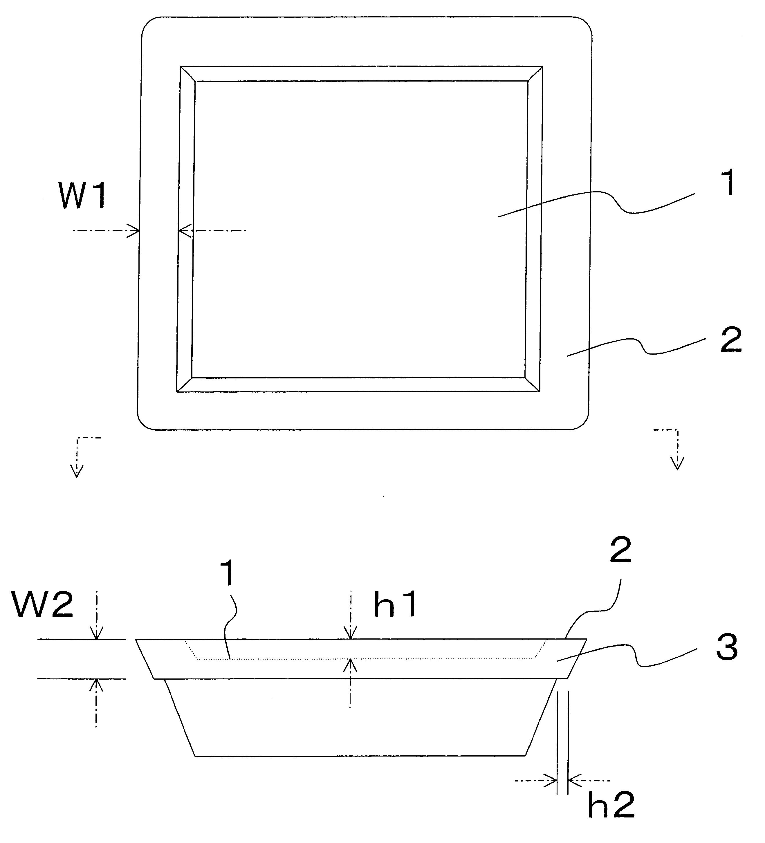
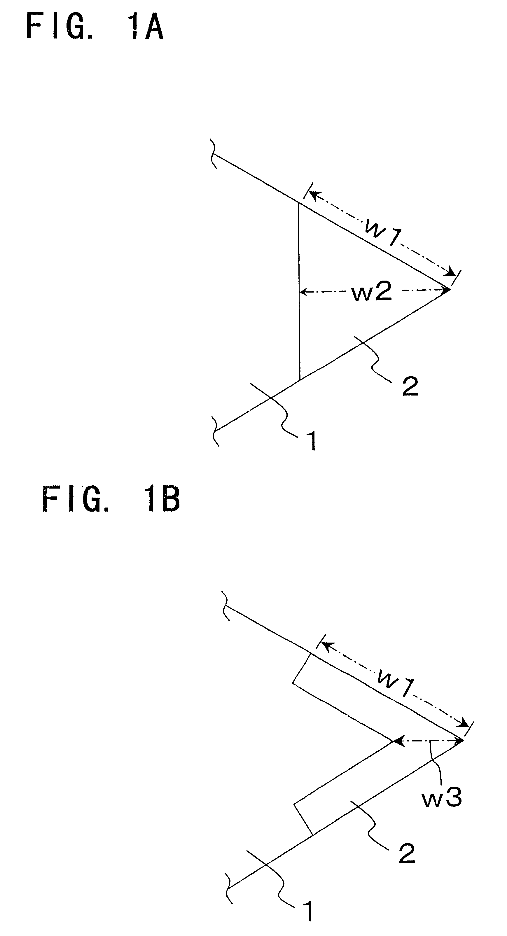
The relation between the length of a diagonal line of the rake surface of the substrate and the warping is explained. If the amount of warp is larger than the step...
example b
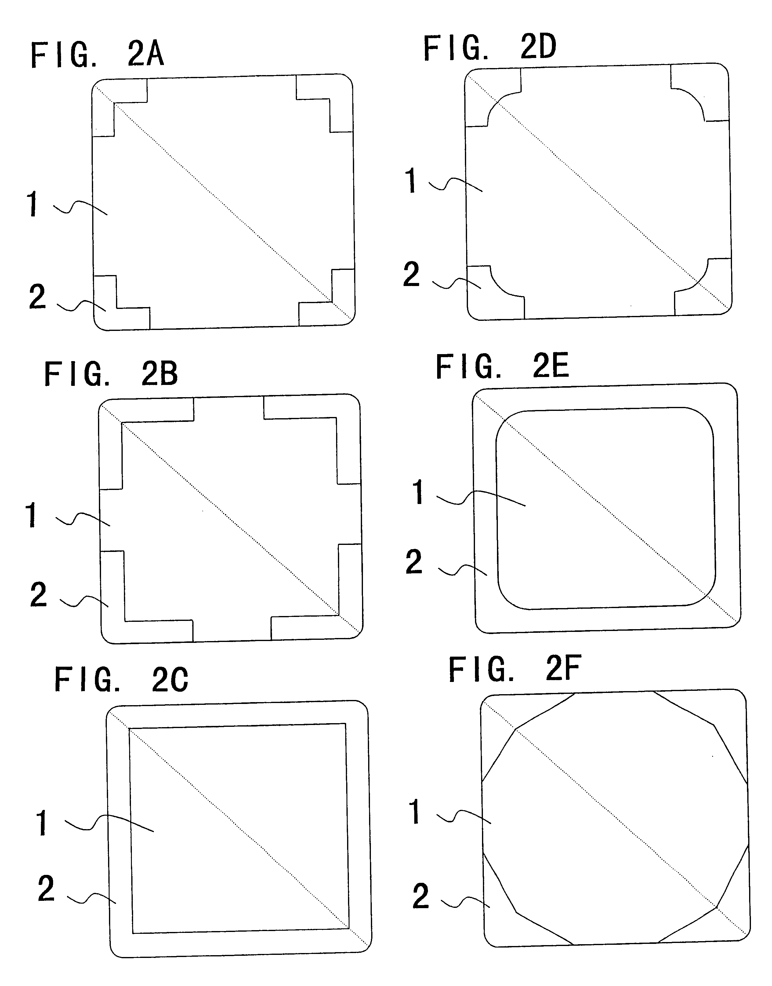
Using starting powders (see Table 4), adjusted at a mixing ratio of the composition B or the composition C of Example A (see Table 1), and a press molding metal die having a convex portion to generate a rake surface of the substrate having a step, a compacted powdered mass having a step at a portion corresponding to the rake surface was prepared by press molding under a pressure of 1.5 ton / cm.sup.2 (approximately 1.47.times.10.sup.4 N / m.sup.2). This compacted powered mass was sintered by a method which is the same as Example A to produce a cemented carbide substrate having the basic shape according to the ISO standard CPGN 120408 with a step shown in FIG. 4 or 5 and with a step on the cuffing edge of the configuration shown in Table 4. Meanwhile, the substrate shown in FIG. 4 has been formed by an electric discharge machine so that a recess will be present at the center of the rake surface, so that a step dimensioned as shown in Table 4 will be formed on the four sides of the rhombu...
PUM
| Property | Measurement | Unit |
|---|---|---|
| height | aaaaa | aaaaa |
| step height | aaaaa | aaaaa |
| step height | aaaaa | aaaaa |
Abstract
Description
Claims
Application Information