High-temperature articles and method for making

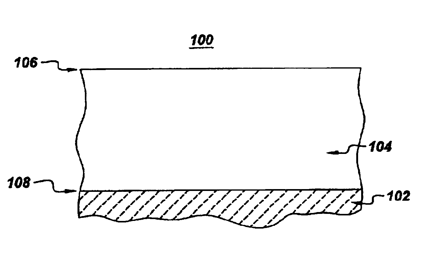
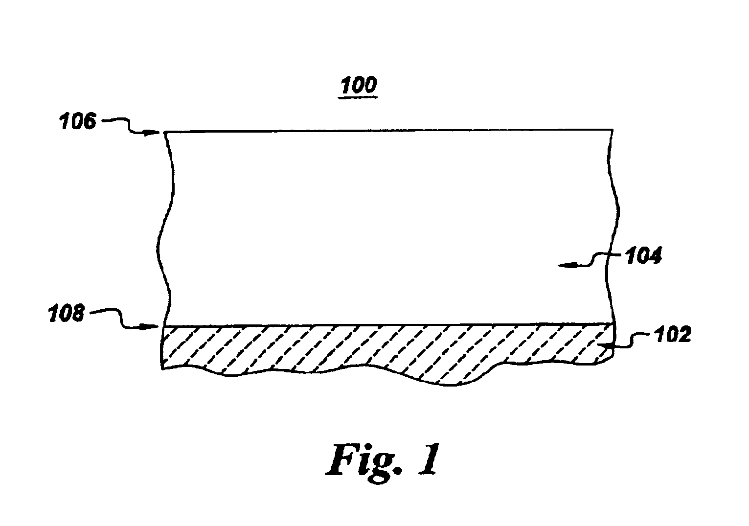
a technology of high-temperature articles and high-temperature components, applied in the direction of magnetic recording, liquid fuel engine components, record information storage, etc., can solve the problems of introducing the risk of additional coating damage, adversely affecting the performance of nickel aluminide-based coatings, and loss of aluminum during deposition, so as to enhance the mechanical and and enhance the oxidation resistance of coatings 104

Inactive Publication Date: 2004-06-08
GENERAL ELECTRIC CO
View PDF13 Cites 5 Cited by
  • Summary
  • Abstract
  • Description
  • Claims
  • Application Information

AI Technical Summary

Benefits of technology

Coating 104 serves to protect substrate 102 from the highly oxidative environment encountered in such structures as turbine assemblies, reactors, boilers, and the like. Coating 104 is substantially a single phase, meaning at least about 80% of coating by volume comprises a single phase. In one embodiment, the single phase of coating 104 comprises a nickel aluminide having a B2 crystal structure. Coating 104 comprises nickel (Ni) and at least 30 atomic percent aluminum (Al). The concentration of aluminum in coating 104 varies from a first concentration at an outer surface 106 of coating 104 to a second concentration at an interface 108 between coating 104 and substrate 102, wherein the first concentration of aluminum is greater than the second concentration of aluminum. Thus, coating 104 has a concentration gradient of aluminum across its thickness. The second concentration is at least 30 atomic percent. Having a gradient in aluminum concentration within the coating advantageously provides aluminum-rich material at the outer surface 106 surface of the coating, where degradation mechanisms such as oxidation act to deplete the material of oxidation-resisting components, of which aluminum is an example. Thus, the gradient in aluminum concentration serves to enhance the oxidation resistance of the coating by placing more aluminum in the region in which it is most needed.
In further embodiments, coating 104 further comprises at least one of chromium (Cr), zirconium (Zr), cobalt (Co), and iron (Fe). Cobalt and iron, when present, are generally substituted for Ni, and may each be present in coating 104 in a concentration of up to about 20 atomic percent. In some embodiments, chromium is present in coating 104 at a concentration of up to about 15 atomic percent to further enhance the oxidation resistance of coating 104. In particular embodiments, chromium is present in coating 104 at a concentration in the range from about 4 atomic percent to about 12 atomic percent. Zirconium, in some embodiments, is present in coating 104 at a concentration of up to about 2 atomic percent, to further enhance the mechanical and oxidation resistance properties of coating 104. In one embodiment, zirconium is present in coating 104 in a concentration in the range from about 0.2 atomic percent to about 0.8 atomic percent.
In further embodiments of the present invention, the second coating layer is reacted with the first coating layer to form reacted coating layer 104 (also referred to herein as coating 104). In one embodiment, reacted coating layer 104 is formed by heat treating first coating layer, second coating layer, and substrate 102 to a temperature in a range from about 700.degree. C. to about 1200.degree. C. for a time period ranging from about 0.5 hour to about 4 hours to react the first layer with the second coating layer. This heat treatment step is performed subsequent to the disposition of the second layer as described previously. Alternatively, coating 104 may be formed by reacting the first coating layer and the second coating layer by in situ heating during deposition of the second coating layer. The in situ heating causes the second coating layer, which is predominantly aluminum, to diffuse into the first coating layer; the predominately aluminum material then reacts with the first coating layer to form coating 104. Such in situ heating may be achieved by electron beam heating during physical vapor deposition of the second layer, or by applying a bias voltage to substrate 102 during ion plasma deposition of the second layer. The coating 104 formed by reacting the first coating layer and second coating layer is, in some embodiments, substantially single phase, the single phase comprising in particular embodiments an intermetallic aluminide compound having a B2 crystal structure. The second coating layer provides an Al-rich cap to the first coating layer, improving high-temperature coating performance by covering the aforementioned microstructural defects, such as surface-connected coating defects, cracks, and oxygen-permeable second-phase stringers, in coating 104 and raising the aluminum content in coating 104.

Problems solved by technology

Performance of the nickel aluminide-based coating is adversely affected by surface-connected coating defects, cracks, and oxygen-permeable second-phase stringers.
Grit blasting and shot-peening have been applied with marginal success to heal defects; but such techniques introduce the risk of additional coating damage.
In addition to surface defects, the physical vapor deposition processes (also referred hereinafter as "PVD") that are used to deposit nickel aluminide-based coatings frequently result in the loss of aluminum during deposition.
The success of such corrective attempts has been limited by problems with castability and ductility of the PVD source, coating adhesion, coating contamination, and chemistry control.
The present approaches have not been successful in either healing surface defects or compensating for lost aluminum in such nickel aluminide-based coatings.
Consequently, nickel aluminide-based coatings often do not provide adequate protection for the underlying alloy substrates in such harsh environments.

Method used


Image

  • High-temperature articles and method for making
  • High-temperature articles and method for making

Examples


Embodiment Construction

The following description is intended to further illustrate the advantages of certain exemplary embodiments of the present invention, and should not be construed as limiting the scope of the invention. Two groups of superalloy substrates were each coated with an about 40 micrometer thick layer of NiCrAlZr alloy, using ion plasma deposition (IPD). In one group, herein referred to as "Group A," the coating composition was, in atomic percent, about 33% Al, about 10% Cr, about 0.5% Zr, and the balance Ni. In the other group, herein referred to as "Group B," the coating composition was, in atomic percent, about 35% Al, about 5% Cr, about 1.2% Zr, and the balance Ni. For each group of substrates coated, a subset was further coated with a about 10 micrometer thick layer of material consisting essentially of aluminum using IPD. After deposition, the coated samples were subjected to a vacuum heat treatment of two hours at 1100.degree. C. to form a single-phase reacted coating layer of B2-str...


PUM

PropertyMeasurementUnit
thicknessaaaaaaaaaa
thicknessaaaaaaaaaa
thicknessaaaaaaaaaa

Abstract

A coated article, a coating for protecting an article, and a method for protecting an article are provided. The article comprises a metallic substrate and a substantially single-phase coating disposed on the substrate, wherein the coating comprises nickel (Ni) and at least about 30 atomic percent aluminum (Al); the coating further comprises a gradient in Al composition, the gradient extending from a first Al concentration level at an outer surface of the coating to a second Al concentration level at an interface between the substantially single-phase coating and the substrate, wherein the first Al concentration level is greater than the second Al concentration level and the second concentration level is at least about 30 atomic percent Al.

Description

BACKGROUND OF INVENTIONThis invention relates to oxidation resistant coatings. More particularly, this invention relates to articles having a coating that is resistant to failure in high temperature oxidative environments and methods of protecting an article in a high temperature, oxidative environment.Nickel (Ni), cobalt (Co), and iron (Fe) based alloys are frequently used to form articles designed for use in high temperature, highly oxidative environments. Such articles include components that are used in turbine systems, such as, but not limited to, aircraft turbines, land-based turbines, marine-based turbines, and the like. To survive in such environments, articles made of these alloys often require coatings to protect the underlying alloys against oxidation and / or hot corrosion. The coating, which is frequently a nickel aluminide (NiAl)-based material, can also be used to provide adherence to an outer thermal barrier coating, where such a coating is employed.Performance of the ...

Claims


Application Information

Patent Timeline
Patent Type & Authority Patents(United States)
IPC IPC(8): C23C28/02C23C4/08C23C26/00F01D5/28C23C14/14C23C14/16C23C30/00F01D25/00F02C7/00F23R3/42
CPCC23C4/085C23C28/023F01D5/28C23C28/028C23C26/00Y10T428/12493F05C2201/0466Y02T50/67F05D2300/121Y10T428/263Y10T428/12944Y10T428/12771Y10T428/12736Y10T428/265Y10T428/1275Y10T428/12458C23C4/073Y02T50/60
Inventor ZHAO, JI-CHENGLIPKIN, DON MARK
Owner GENERAL ELECTRIC CO
Why Eureka
Try Eureka