Hazardous waste disposal

a waste disposal and hazardous technology, applied in vacuum distillation separation, oxygen compound purification/separation, separation processes, etc., can solve the problems of increasing erosion and corrosion, reducing pipeline efficiency, and increasing erosion and corrosion

Inactive Publication Date: 2004-08-10
MOORE JR JOHN W
View PDF15 Cites 8 Cited by
  • Summary
  • Abstract
  • Description
  • Claims
  • Application Information

AI Technical Summary

Benefits of technology

An improved process of refining TEG is provided in which the unit is a mobile self contained unit that will purify the spent TEG by substantially reducing the amount of entrained solids and hydrocarbons. The refining unit can also be used to clean contacting towers, heat exchangers, pumps, still column, reboiler and surge tanks of TEG dehydrators. This will provide a 97% volume reduction in hazardous wastes compared to conventional methods of cleaning dehydrators. The unit accomplishes this with vacuum distillation incorporating a closed system. The refining unit utilizes the TEG located at the site along with a chemical degreaser that aids in the removal of coke and sludge buildups. All contaminants and foulants that are removed from the contacting tower of the dehydration system are removed by the refining unit. The unit eliminates the risk of hazardous waste spills that commonly occur with conventional cleaning methods of dehydration systems. All wastes that occur during cleaning and refining are gathered in the refining unit. These wastes can be collected very easily to be disposed of properly. The refining unit will provide efficient cleaning of dehydration equipment, reduce hazardous waste volume, convert hazardous waste into a useful product, reduce the emission of dangerous VOC's and BTEX all without shutting in gas sales. The refining unit is able to accomplish this since it is a closed system. The unit can utilize dehydrated gas or LPG at the site for fuel gas for the burner, power medium used in the operation of valves, shutdowns and fluid transfer.
Other objects are to achieve the above with a method that is rapid, versatile, ecologically compatible, energy conserving, efficient, and inexpensive, and does not require highly skilled people to install, operate, and maintain.

Problems solved by technology

If these elements remain in the gas stream they will cause numerous problems in the pipeline and processing equipment.
Hydrates will decrease pipeline efficiency and cause shutdowns.
The hydrates will also increase erosion and corrosion.
In normal use a supply of TEG will run for several months before it gets so laden with impurities that it is no longer efficient to continue use.
Many of the contaminants are hazardous materials requiring expensive limitations upon their disposal.
Those in the art will understand that the dehydrators become loaded with contaminants which are hazardous, which in turn, requires expensive disposal.
The problems encountered with TEG dehydrators is that along with water, the TEG starts to pick up small amounts of light liquid hydrocarbons.
As the TEG becomes more saturated, contaminants and hydrocarbons are increasingly more difficult to remove in the regeneration process.
They are environmentally hazardous and considered carcinogens.
Another source of contamination to the TEG system is salts.
Carry over of brine solutions from the field can lead to salt contamination in the TEG system.
Sodium salts (typically sodium chloride) are a source of problems in the reboiler since sodium chloride is less soluble in hot TEG than in cool TEG.
The salt can deposit on the fire tube restricting heat transfer, causing the temperature of the fire tube increase, which will lead to thermal degradation of the TEG.
The salt will also increase corrosion of the fire tube.
The dissolved salts cannot be removed by mechanical filtration.
After a period of time, the TEG becomes severely contaminated and loses its effectiveness as a desiccant and is considered "spent".
TEG at 94% concentration in solution becomes increasingly ineffective as a desiccant.
The presence of contaminants may result in fouled equipment, foaming, poor dehydration and the potential of increased release of pollutants into the atmosphere.
(Both of which are not very economic and will require the dehydration system to be shutdown.)
During these down times operators currently choose to clean the dehydration system at considerable costs, which produces large amounts of hazardous waste to be disposed of.
This also increases the chance of spilling the hazardous waste onto the ground causing more problems.
However, to obtain extremely low absolute pressures is difficult and expensive.

Method used


Image

  • Hazardous waste disposal
  • Hazardous waste disposal
  • Hazardous waste disposal

Examples


Embodiment Construction

)

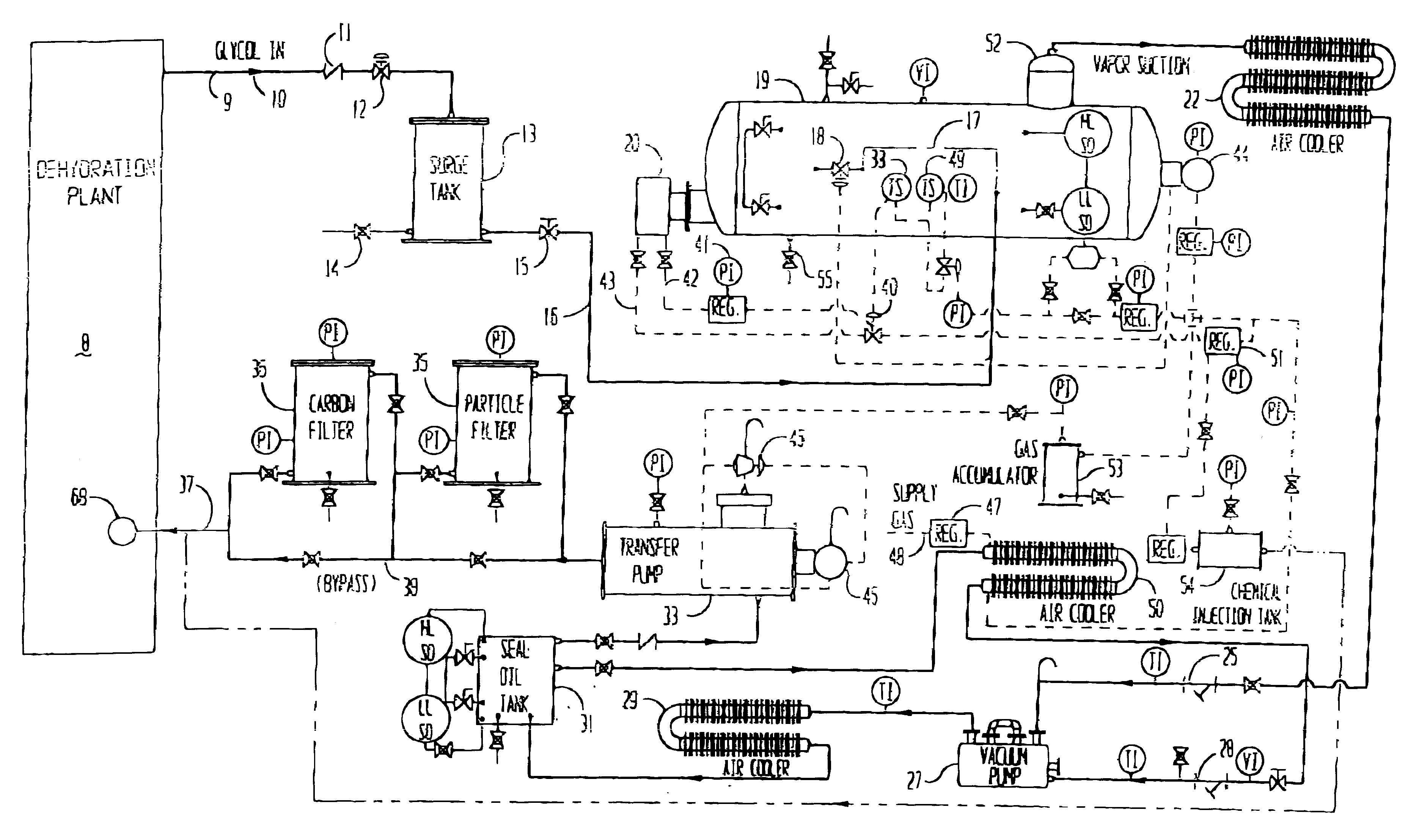
When used with a natural gas dehydration plant this invention is designed to remove impurities from TEG.

Referring to FIG. 1 there is shown a schematic flow sheet showing the equipment for the glycol refining process embodying the present invention. The processing of the contaminated glycol can be conducted on a batch or semi batch process. Spent TEG is brought into the system by vacuum and / or gravity. The natural gas dehydration plant 8 is a source 9 of contaminated TEG for the refining equipment. The spent glycol enters the system in a conduit 10 that then passes through a check valve 11. The spent glycol then flows through the inlet control valve 12 and into the surge tank 13. The inlet control valve 12 is controlled by high and low level shutdowns located in vacuum reboiler or evaporator 19 and seal oil tank 31. When a low or high level shutdown occurs the inlet control valve 12 is shut and a temperature switch 49 cuts off the fuel supply to burner 20.

After the spent TEG is rece...


PUM

PropertyMeasurementUnit
temperatureaaaaaaaaaa
temperaturesaaaaaaaaaa
temperatureaaaaaaaaaa

Abstract

Contaminated glycol is refined by vacuum distillation. Specifically the evaporator is heated to a temperature below the degradation temperature of the glycol. The vacuum is used to bring the flashpoint down sufficiently so that glycol evaporates or flashes at that temperature. The glycol is condensed and filtered through activated granular carbon. The principal use of refining the glycol is to refine the triethylene glycol used in natural gas dehydration plants. For such purposes the equipment is mounted upon a trailer to be taken to the plant for cleaning glycol. In such instance, in addition to refining the glycol, a cleaning agent (which contains a degreaser) is added to the refined glycol. The glycol is refined while the natural gas dehydration plant is in normal operation and therefore it is not necessary to stop the natural gas dehydration plant for refining the glycol used therein. In addition, by the addition of the cleaning agent, the dehydrating plant equipment may be cleansed of hazardous waste. The hazardous waste will be separated and concentrated in the distillation. Therefore, the transportation of the hazardous waste to a disposal location is simplified.

Description

(1) Field of the InventionThis invention relates to recycling of fluids which have been polluted or contaminated. The majority of the fluids treated according to this invention are used in natural gas treating plants, primarily Triethylene Glycol (also called TEG). In addition, ethylene glycol and diethylene glycol, which find use as anti-freeze, also accumulate hazardous material and are recycled by this process.Operators of natural gas dehydration and treatment plants will have ordinary skill in this art.(2) Description of the Related ArtNatural gas flowing from wells may contain water vapor, liquid water, brine solution, heavy and light hydrocarbons, and particulate matter such as sand, pipeline scale and rust. If these elements remain in the gas stream they will cause numerous problems in the pipeline and processing equipment. Treating natural gas will commonly occur at individual wells, gathering systems, compressor stations, distribution stations, and gas processing units. Low...

Claims


Application Information

Patent Timeline
Patent Type & Authority Patents(United States)
IPC IPC(8): B01D3/14B01D3/06B01D3/10C07C27/28
CPCB01D5/006
Inventor MOORE, JR., JOHN W.
Owner MOORE JR JOHN W
Why Eureka
Try Eureka