
High temperature decomposition of hydrogen peroxide

a hydrogen peroxide and high temperature technology, applied in the direction of nitrogen oxide/oxyacids, separation processes, nitrous oxides, etc., can solve the problems of high processing cost, high cost and complexity, complex effect of nitric oxide removal from gas stream, etc., to achieve low water solubility, increase the effectiveness of water scrubber systems, and improve water soluble

Inactive Publication Date: 2004-09-21
NAT AERONAUTICS & SPACE ADMINISTATION U S GOVERNMENT AS REPRESENTED BY THE ADMINISTATION OF
View PDF12 Cites 25 Cited by
  • Summary
  • Abstract
  • Description
  • Claims
  • Application Information

AI Technical Summary

Benefits of technology

Power plants produce a large amount of nitric oxide that must be removed from exhaust gas streams before the gas stream may be emitted into the environment. Effective removal of nitric oxide from the gas stream is complicated by its low water solubility. Although water scrubber systems may be used to aid in the removal of nitric oxide from the gas streams, the effectiveness of the water scrubber system may be increased by oxidizing the nitric oxide to nitrogen dioxide. Nitrogen dioxide is more water soluble than nitric oxide and can be easily removed from the gas streams using various removal processes, such as the water scrubber systems. Although nitric oxide does slowly oxidize in air to nitrogen dioxide, an effective oxidizing agent is needed to make the oxidation of nitric oxide effective at low concentrations (.about.50 to 350 ppm). This low concentration of NO represents a target planned by the US EPA for power plant applications. By 2004, the EPA will require that coal and oil fired power plants install new controls that lower the NOx emissions to 110 ppm. The 2004 requirement for natural gas NOx emissions will be lowered in 2004 to 50 ppm. Currently, the Selective Catalytic Reduction (SCR) method is the only technology that can meet these 2004 EPA requirements.
Gas-phase oxidation of nitric oxide to nitrogen dioxide may be increased by using ozone, hydrogen peroxide, atomic oxygen, hydroxyl radicals or hydroperoxyl radicals as oxidizing agents. The problems with these materials are their high cost and complexity. Injection of hydrogen peroxide in a heated (300 to 400.degree. C.) nitric oxide gas stream or the introduction of an ultraviolet light source to decompose hydrogen peroxide to form oxidative free radicals are examples of known technology with high processing costs. Another expensive material that has been used to oxidize nitric oxide is ozone. A need therefore exists for a highly effective and low cost method for oxidation of nitric oxide.
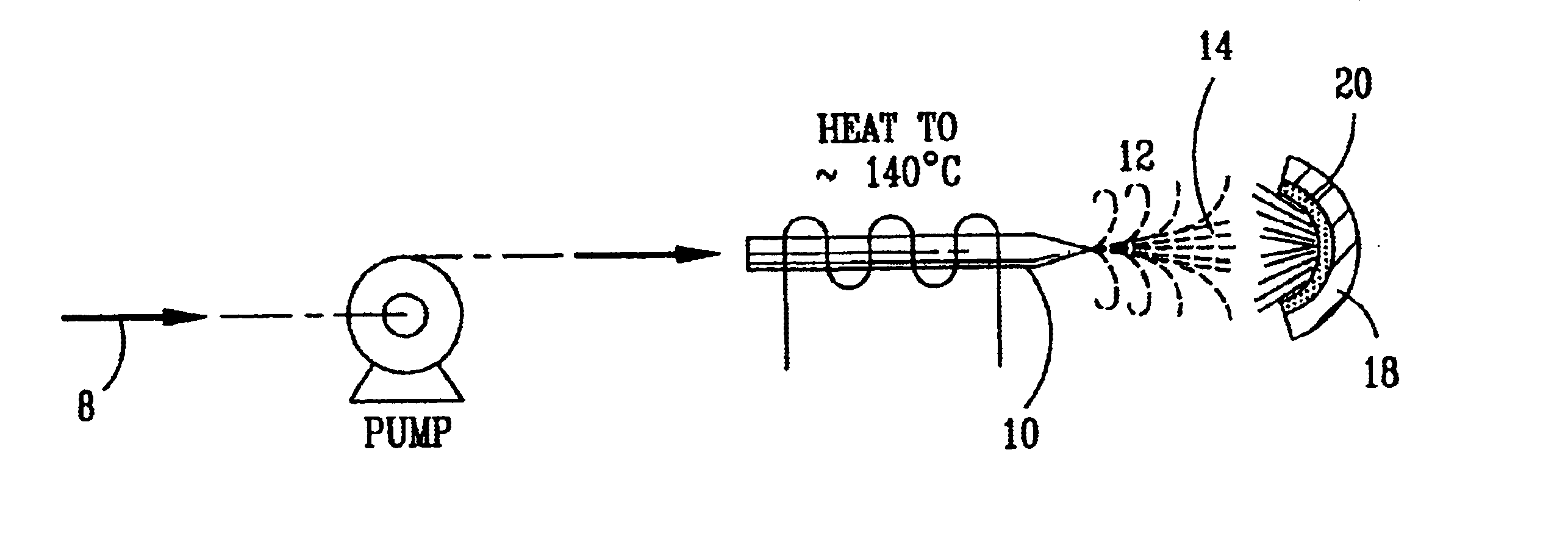
To overcome the foregoing problems, the subject invention provides a method and apparatus wherein a hydrogen peroxide solution is directed onto a heated surface in a nitric oxide stream so that the hydrogen peroxide is decomposed to form oxidative free radicals, hydroxyl and hydroperoxyl, for the oxidation of the nitric oxide. The hydrogen peroxide solution is preferably delivered to the heated surface through a nozzle, which may also be heated, to increase the concentration of and thereby enrich the hydrogen peroxide solution. Impinging the enriched hydrogen peroxide solution onto a heated surface accelerates the decomposition of hydrogen peroxide. Because the rapid decomposition of hydrogen peroxide occurs on the heated surface, there is no increased risk of explosion of stored hydrogen peroxide solution. Since the high temperature decomposition of hydrogen peroxide to oxidative free radicals, hydroxyl and hydroperoxyl, occurs in a stream of nitric oxide, distribution of the oxidative free radicals in the stream will cause rapid gas-phase oxidation of the nitric oxide to nitrogen dioxide.
This high temperature decomposition process provides a simple way for increasing the instability of hydrogen peroxide to the point of decomposition. The process only requires a small pump, a nozzle, a heated surface, and an optional heated tube. There is no need to heat the gas stream that contains the nitric oxide or to introduce an ultraviolet light source or ozone generator.
This process may be used in small scrubbers or large scrubbers similar to those found in power plants. The basic unit is the same for both applications, but the power plant would use multiple units distributed across the flue stack. The commercial potential for this high temperature decomposition process when used in combination with a wet scrubber for nitrogen dioxide is very large. Power plant applications that control NOx emission are estimated to cost in the billions of dollars. This process is the key to making current technology effective in controlling low-level emissions of nitric oxide found in power plants worldwide.

Problems solved by technology

Effective removal of nitric oxide from the gas stream is complicated by its low water solubility.
The problems with these materials are their high cost and complexity.
Injection of hydrogen peroxide in a heated (300 to 400.degree. C.) nitric oxide gas stream or the introduction of an ultraviolet light source to decompose hydrogen peroxide to form oxidative free radicals are examples of known technology with high processing costs.
Another expensive material that has been used to oxidize nitric oxide is ozone.

Method used


Image

  • High temperature decomposition of hydrogen peroxide
  • High temperature decomposition of hydrogen peroxide
  • High temperature decomposition of hydrogen peroxide

Examples


example 1

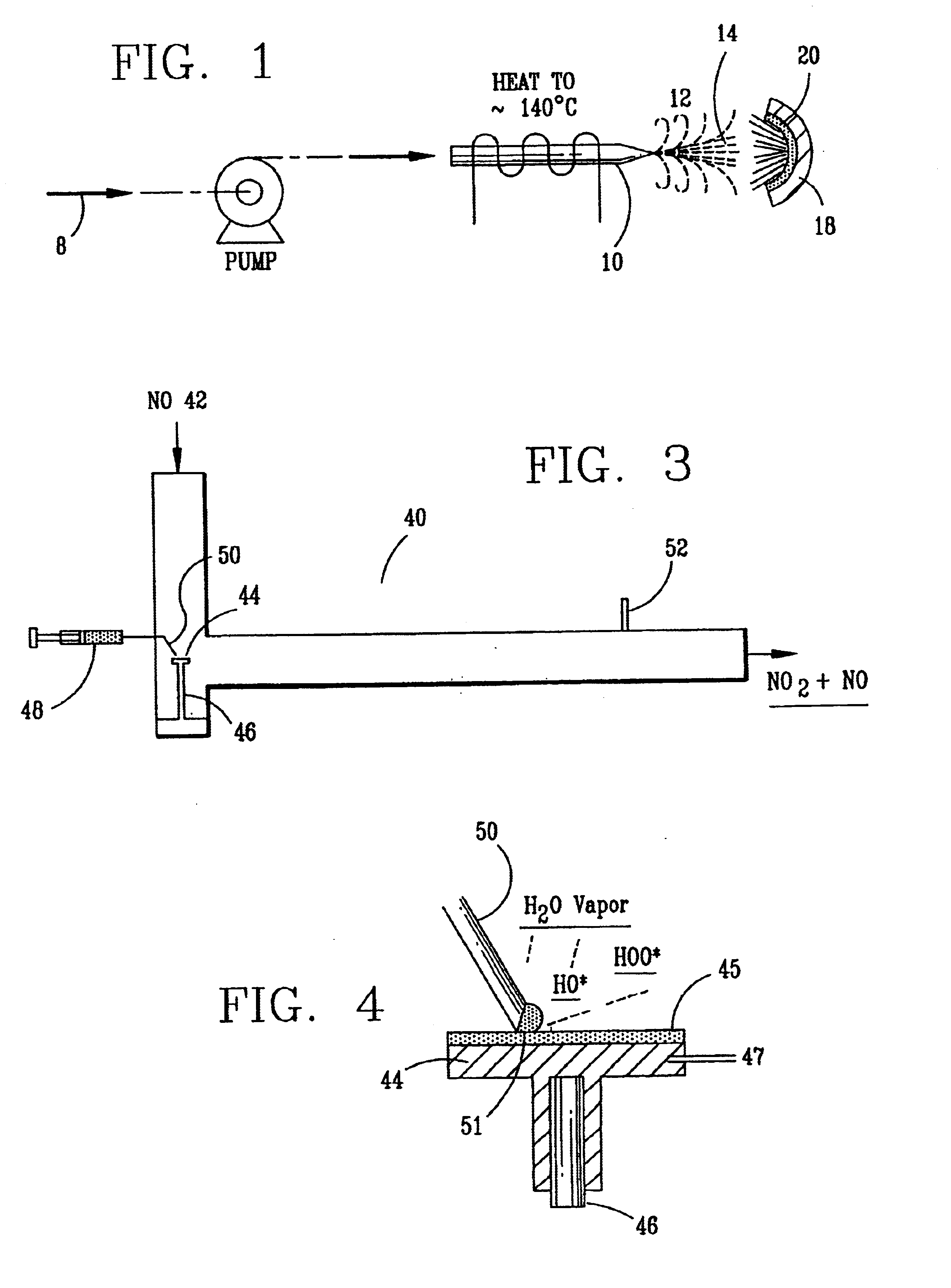
A laboratory scale breadboard version of the subject high temperature decomposition process was used to confirm the conversion of NO to NO.sub.2 when exposed to oxidative free radicals generated from the decomposition of hydrogen peroxide on a heated surface having a catalytic coating. In this example, a compressed gas cylinder that contained 5000-ppm nitric oxide in nitrogen was connected to a flow controller adjusted to provide 0.2 liters per minute of the mixture. The output of the flow controller was mixed with the output from a second flow controller that provided 4.8 liters per minute of nitrogen. The resulting mixture, which had a concentration of 200 ppm of NO was introduced into a test fixture 40 as illustrated in FIGS. 3 and 4. The test fixture 40 was fabricated from 2-inch clear PVC tubing that directed the test gas mixture 42 of 200 ppm NO over a mild steel block 44 with a 0.44 square-inch surface area that had an oxidized catalytic coating 45 (iron oxide) or a small sta...

example 2

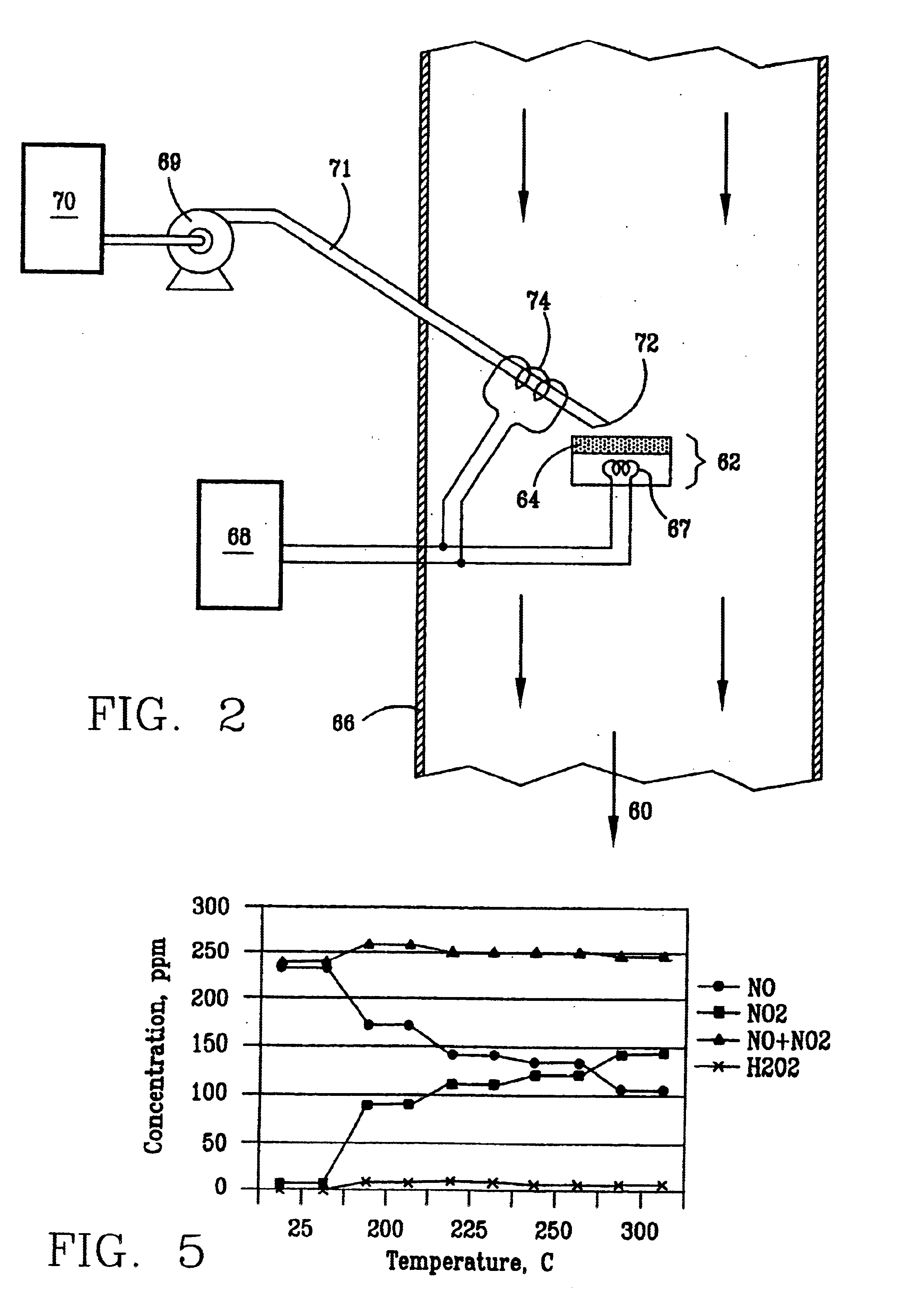
For power plant applications the concentration of NO is typically in the 200-300 ppm range, which represents about 90 percent of the total NOx emissions with the remainder being primarily NO.sub.2. Assuming that the total flow of the gas stream containing NO through the flue gas stack is 1,000,000 cfm, the amount of hydrogen peroxide can be calculated as follows:

This example starts with a 50% hydrogen peroxide solution and passes it through a check valve to prevent back-flow. Then, the hydrogen peroxide solution is heated to raise the temperature to approximately 140.degree. C. as illustrated in FIG. 1. The heat vaporizes some of the water in the hydrogen peroxide solution and produces an enriched hydrogen peroxide solution and steam. The steam and the enriched hydrogen peroxide solution are impinged onto a heated (200-500.degree. C.) surface. The heated surface in this example is covered by a catalytic coating of iron oxide because it produces a high degree of conversion. The resul...


PUM


Abstract

Nitric oxide (NO) is oxidized into nitrogen dioxide (NO2) by the high temperature decomposition of a hydrogen peroxide solution to produce the oxidative free radicals, hydroxyl and hydroperoxyl. The hydrogen peroxide solution is impinged upon a heated surface in a stream of nitric oxide where it decomposes to produce the oxidative free radicals. Because the decomposition of the hydrogen peroxide solution occurs within the stream of the nitric oxide, rapid gas-phase oxidation of nitric oxide into nitrogen dioxide occurs.

Description

ORIGIN OF THE INVENTIONThe invention described herein was made by an employee of the United States Government and may be manufactured and used by or for the Government of the United States of America for governmental purposes without the payment of any royalties thereon or therefor.1. Field of the InventionThis invention relates generally to a method and apparatus for the high temperature decomposition of hydrogen peroxide to form oxidative free radicals, such as, hydroxyl radical (HO.) and hydroperoxyl radical (HOO.), which oxidize nitric oxide (NO) to nitrogen dioxide (NO.sub.2).2. Description of the Background ArtPower plants produce a large amount of nitric oxide that must be removed from exhaust gas streams before the gas stream may be emitted into the environment. Effective removal of nitric oxide from the gas stream is complicated by its low water solubility. Although water scrubber systems may be used to aid in the removal of nitric oxide from the gas streams, the effectiven...

Claims


Application Information

Patent Timeline
IPC IPC(8): B01D53/76B01D53/74B01D53/56C01B21/00C01B21/36C01B13/02
CPCB01D53/56B01D53/76C01B13/0214C01B21/36
Inventor PARRISH, CLYDE F.
Owner NAT AERONAUTICS & SPACE ADMINISTATION U S GOVERNMENT AS REPRESENTED BY THE ADMINISTATION OF
Learn More