Methods and apparatus for increasing and extending oil production from underground formations nearly depleted of natural gas drive

a technology of natural gas drive and underground formations, which is applied in the direction of liquid separation auxiliary apparatus, combination devices, feed/discharge of settling tanks, etc., can solve the problems of limited success, high pressure to form in oil and gas basins, and now mostly depleted fields

Inactive Publication Date: 2004-10-26
HYDROTREAT
View PDF35 Cites 23 Cited by
  • Summary
  • Abstract
  • Description
  • Claims
  • Application Information

AI Technical Summary

Benefits of technology

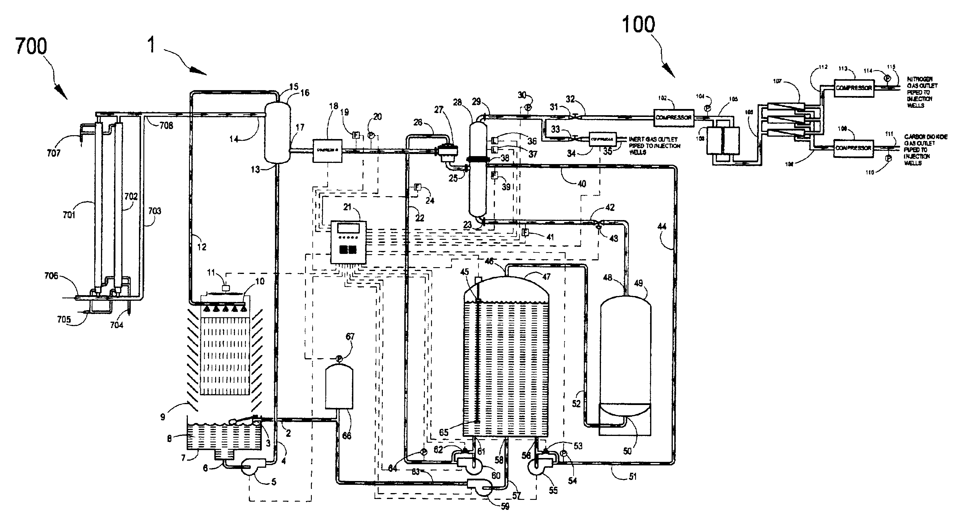
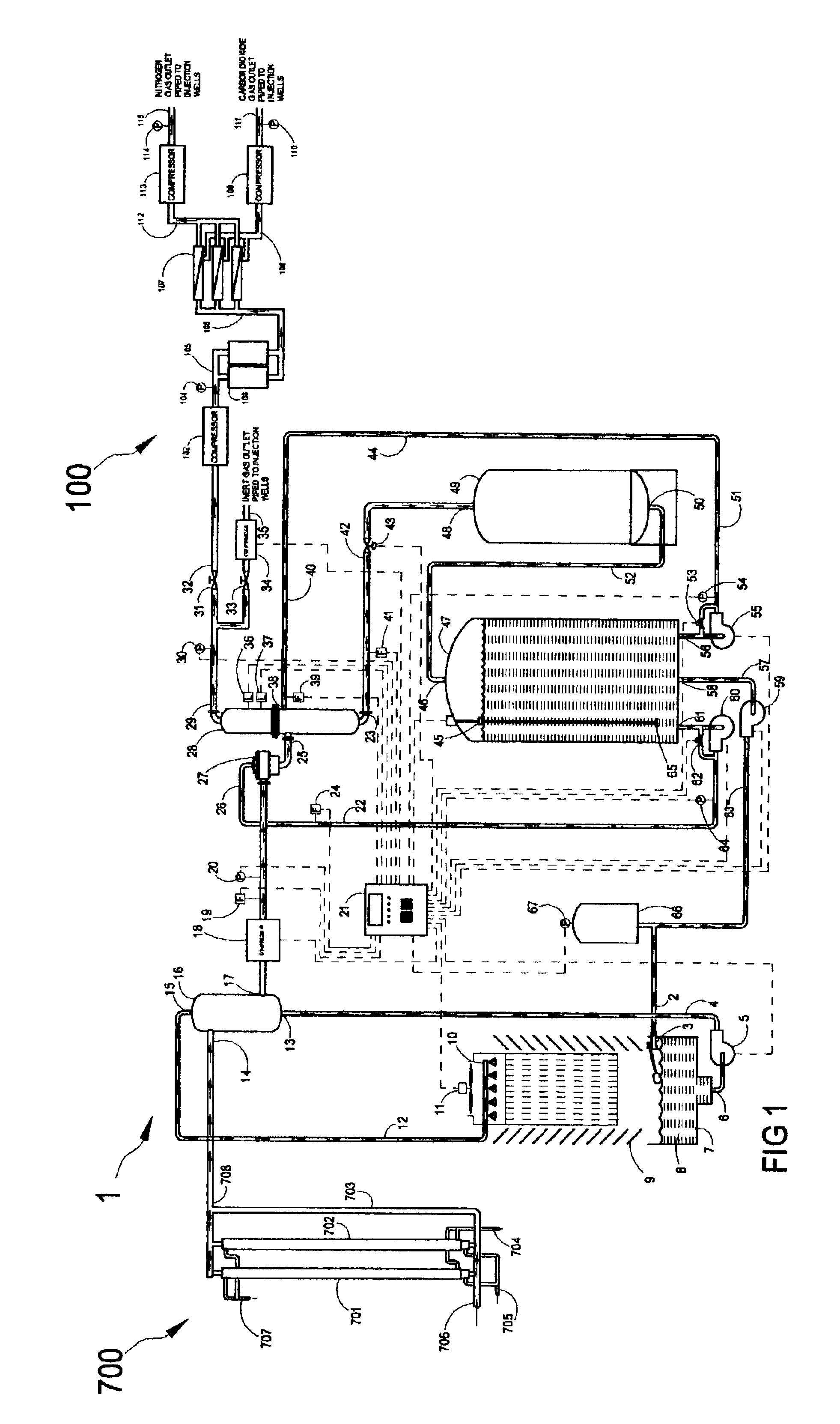
Shallow oil producing formations frequently contain oils with higher viscosities than the deeper wells where the volatile products may not generally escape. The viscosity of heavy oils can be reduced by absorption of carbon dioxide (CO.sub.2). Where it is determined from laboratory analysis that the reduction of oil viscosity of the oil in the underground formations would be economically beneficial to the production process, carbon dioxide can be separated from the nitrogen gas to nearly 100 percent of the--injection gases to reduce the viscosity of heavy oils. The nitrogen gas can be released to the atmosphere, transported to other oilfields for injection, or used for injection in another part of the oil formation under production as a driving mechanism when the carbon dioxide gas has reduced the heavy oil viscosity. Membranes may be used to separate the nitrogen from the carbon dioxide in flue gases. The membranes are typically employed for production of nitrogen gas with air as the source of nitrogen. The membrane used are assemblies of many thousands of hollow polymeric fibers each approximately the size of a human hair with the inside surface treated to produce a thin film on the inside surface that actually becomes the membrane that allows oxygen molecules to flow through the membrane and reject the larger nitrogen molecules. The porous material below the membrane surface serves as a support. The membranes also allow other gases with molecules smaller than that of nitrogen to flow through and be separated from the nitrogen gas. The result is for pure nitrogen to be separated from all other gases, including water vapors, in atmospheric air. In applications other than oil production the nitrogen is collected and stored, with the gases other than nitrogen typically discharged to the atmosphere. For injection into a heavy oil formation the flue gases can be separated for concentration of carbon dioxide where it is beneficial and economically feasible to do so. The normally discarded gases that flow through the membranes become the product to be collected for injection into the underground heavy oil formation.
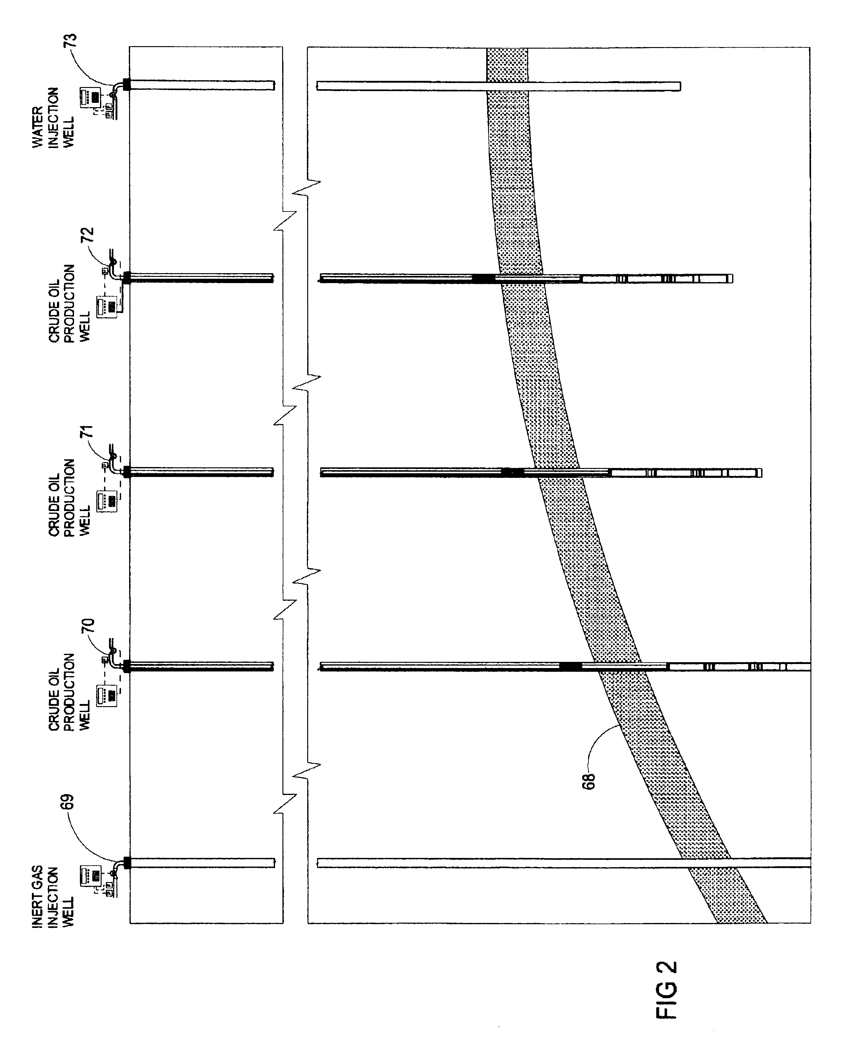
The present invention provides a new method and apparatus for increasing the rate of production and the total amount of oil that can be extracted from underground formations nearly depleted of natural gas as a driving mechanism by injecting inert gases as the oil driving mechanism with water as a gas blocking mechanism to increase the subterranean pressure and drive the oil to production wells where it can be brought to the surface.
The gas separation system may employ a membrane system to separate the carbon dioxide gas from the nitrogen gas obtained from the engine exhaust gases to inject a high concentration of carbon dioxide gas into an underground formation to reduce the viscosity of heavy oils and increase their ability to flow followed by injection of the nitrogen gas to drive the oils to the production wells where they can be brought to the surface.
The injection well system used to deliver the inert gases and water to the underground formation may include a well lined with a casing, a casing head at the surface, pressure and flow sensors, a flow control valve, and a controller to monitor and sequence the injection operation in accordance with the present invention. A second embodiment of the injection system used to deliver the inert gases and water to the underground formation may include a well lined with a casing, a casing head at the surface, a separate injection pipe inserted into the well casing with a packer above the production formation and perforated at the level of highest permeability in the production formation to reduce the volume of gas and water retained in the casing, avoid losing the injection gases through holes in the casing, and avoid having to drive a large volume of water otherwise collected in the casing back through the formation.

Problems solved by technology

The weight of the layers of material that accumulated on top of the sand beds and the high density of the saltwater caused a high pressure to form in the oil and gas basins.
The actions of the salt left porous layers of rock turned upward against the impervious salt, formed pockets in the cap of the domes, and caused faults in the strata above or surrounding the domes to trap the migrating oil and gas.
Water and steam pumped down into the oil-bearing formations under ground as a driving mechanism (water and steam flooding) has received a limited amount of success for extraction of additional oil from certain fields.
Many of those fields are now mostly depleted of the oil considered to be recoverable.
A second problem experienced in the attempts at inert gas injection was the corrosive effects of flue gases on the equipment and piping both above and below ground.
With the natural gas nearly depleted over the oil in the underground formations where the oil production is to occur methane for engine fuel may not be readily available in the oilfields.
The cost of a natural gas (methane) pipeline or the trucking of propane to some of the oilfields may be substantial.

Method used


Image

  • Methods and apparatus for increasing and extending oil production from underground formations nearly depleted of natural gas drive
  • Methods and apparatus for increasing and extending oil production from underground formations nearly depleted of natural gas drive
  • Methods and apparatus for increasing and extending oil production from underground formations nearly depleted of natural gas drive

Examples


second embodiment

FIGS. 33 and 34 depict in schematic illustrations flow diagrams of the pumping operation of the hydraulically operated crude oil pump 350 in accordance with the present invention. FIG. 33 provides a flow diagram of the hydraulically operated crude oil pump 350 with crude oil being expelled from the upper crude oil pumping section and crude oil being drawn from the underground formation into the lower crude oil pumping section. FIG. 34 provides a flow diagram of the pump with crude oil being expelled from the lower crude oil pumping section and crude oil being drawn from the underground formation into the upper crude oil pumping section. The hydraulically operated crude oil pump 350 consists of an upper crude oil pumping section, a double acting hydraulic cylinder section, a lower crude oil pumping section, and a hydraulic pump and controls driven by an electric motor. The upper crude oil pumping section consists of a bladder 421, an internal bladder space 420 for hydraulic fluid, a ...

third embodiment

FIG. 35 depicts a vertical cross-sectional view of the hydraulically operated crude oil pump 500 employing a diaphragm instead of a bladder as the crude oil pumping mechanism with a mechanical spring to return the diaphragm and draw the crude oil from the production formation in accordance with the present invention. The hydraulically operated crude oil pump 500 consists of a pump cap 503, and upper crude oil pumping section 502, a lower crude oil pumping section 501, a crude oil inlet 214 where crude oil enters the pump, a hydraulic pump and control valve assembly 213, and an electric motor adapter 212.

FIGS. 36-38 provide enlarged cross-sectional views of the various components of the hydraulically operated crude oil pump 500. FIG. 36 provides the cross-sectional views of the pump cap 503 and the upper crude oil pumping section 502. FIG. 37 provides the cross-sectional view of the lower crude oil pumping section 501. FIG. 38 provides cross-sectional views of the crude oil inlet 214...


PUM

PropertyMeasurementUnit
volumeaaaaaaaaaa
volumeaaaaaaaaaa
volumeaaaaaaaaaa

Abstract

Methods and apparatus employing inert gases injected into the lower level of sloping underground oil-bearing formations as a driving mechanism and water injected into the upper level of the formations as a gas blocking mechanism for increasing and extending the production of oil from underground formations is described. Also described is an inert gas oil production system comprising an exhaust gas processing system, a well inert gas and water injection system, an oil production well system, and a fuel gas generator. A hydraulically operated crude oil pump is also described.

Description

1. Field of the InventionThe present invention relates to methods and apparatus employing inert gases injected into the lower level of sloping underground oil bearing formations as a driving mechanism and water injected into the upper level of the formations as a gas blocking mechanism for increasing and extending the production of oil from underground formations nearly depleted of natural gas as a driving mechanism.2. Description of Related ArtDuring geologic times marine animal and vegetable remains collected in ocean basins and were covered by the accumulation of eroded sand and sediment. Over millions of years the organic matter in those saltwater basins changed to what would become oil and gas. The weight of the layers of material that accumulated on top of the sand beds and the high density of the saltwater caused a high pressure to form in the oil and gas basins. Seawater flowing in subterranean strata and other natural forces added to this pressure and caused the oil and gas...

Claims


Application Information

Patent Timeline
Patent Type & Authority Patents(United States)
IPC IPC(8): B01D21/24B03D1/14E21B43/34E21B43/12E21B43/16B01D17/035B01D17/038B01D17/12B01D65/00
CPCB01D21/2433B01D21/245B03D1/14E21B43/122E21B43/128B03D1/028E21B43/166E21B43/34E21B43/129B01D21/302B01D21/34
Inventor ARNAUD, JOHNNYBEARD, B. FRANKLIN
Owner HYDROTREAT
Why Eureka
Try Eureka