
Internal combustion engine

Inactive Publication Date: 2005-01-04
RICH IDEAS CREATED - HLDG
View PDF8 Cites 13 Cited by
  • Summary
  • Abstract
  • Description
  • Claims
  • Application Information

AI Technical Summary

Benefits of technology

It is also contemplated in the subject invention to reduce the volume of the combustion chamber relative to the conventional combustion chamber so that the net power obtained with a delayed closing of the inlet means during the compression stroke is substantially equivalent to a conventional construction, wherein the inlet valve means is closed during the beginning of the compression stroke. However, since the combustion chamber has been substantially reduced, the amount of fuel necessary to obtain a specific compression ratio and a required power output, is considerably reduced.
Because of the effective sealing of the piston in the cylinder and the efficient burning of the pre-heated and pre-mixed air-fuel mixture, pollutants that normally infiltrate into the combustion chamber from the crankcase and from behind the compression rings of the conventional internal combustion engine are eliminated, and thus, the subject invention provides for emissions that are essentially pollution-free.
Accordingly, it is an object of the subject invention to provide an internal combustion engine that substantially eliminates pollution in the emissions thereof, but that increases the efficiency in the operation of the engine to obtain greater MPG ratings, and not only is less fuel consumed but the life of the engine is substantially increased over the life normally expected of the prior known conventional engine.

Problems solved by technology

In the operation of internal combustion engines as located in the present day automotive vehicle, the engine is not only considered to be inefficient in the use of fuel but further is objectionable because of the emission of pollutants to atmosphere.
Inefficient fuel consumption is known to be caused by incomplete combustion due to improper atomization of the fuel molecules and the improper mixture of oil vapors and prior combustion products with air-fuel mixture in the combustion chamber.
This so-called “blow-by” of the gases and vapors through the compression rings normally results because of faulty sealing of the rings, and in most vehicles the gases and vapors which include objectionable hydrocarbons penetrate into the combustion chamber.
Normally such pollutants will not effectively burn on combustion and on the exhaust stroke, the piston pumps out the unburned oxides of nitrogen and hydrocarbons including carbon monoxide as emissions.
This mixture will not effectively burn but may be ignited in the exhaust stroke which causes an increase of temperature in the combustion chamber.
The same circumstances oftentime occur to produce detontation or shock waves that also cause pinging or knocking, thereby resulting in undue engine wear and high temperature in the crankcase and cylinder.
The resulting high temperatures may cause oxygen to combine with nitrogen to produce nitric oxide that is eventually exhausted through the exhaust manifold as a pollutant.
As a result ultraviolet rays may be emitted that tend to produce pre-ignition on the next cycle, and this can further cause detonation and knocking.
One of the common problems in the prior known internal combustion engines is the build up of carbon on the piston head, rings, valves and combustion chamber walls.
In such an instance carbon is burning off the piston head, valve rings and walls, and unless corrected can produce shock waves that could be damaging to the engine.
The creation of shock waves can also interfere with the harmonious movement of the flame front on the power stroke, and interference with the flame front can result in incomplete combustion.
Incomplete combustion may result in the production of hydrocarbons, such as carbon monoxide and sulfer dioxide, and since these gases cannot be converted into energy before the power stroke, they are pumped out into the exhaust system as pollutants instead of being utilized for power.
Some high temperature vapors may remain in the crankcase and will cause the viscosity of the oil to break down therein which eventually will produce engine wear.
Since carbon is abrasive, the mixture thereof with the crankcase oil will eventually result in wear of the engine parts as the parts are lubricated.
The carbon further causes the oil to break down in viscosity which further produces wear on the bearing surfaces.

Method used


Image

  • Internal combustion engine
  • Internal combustion engine

Examples


Embodiment Construction

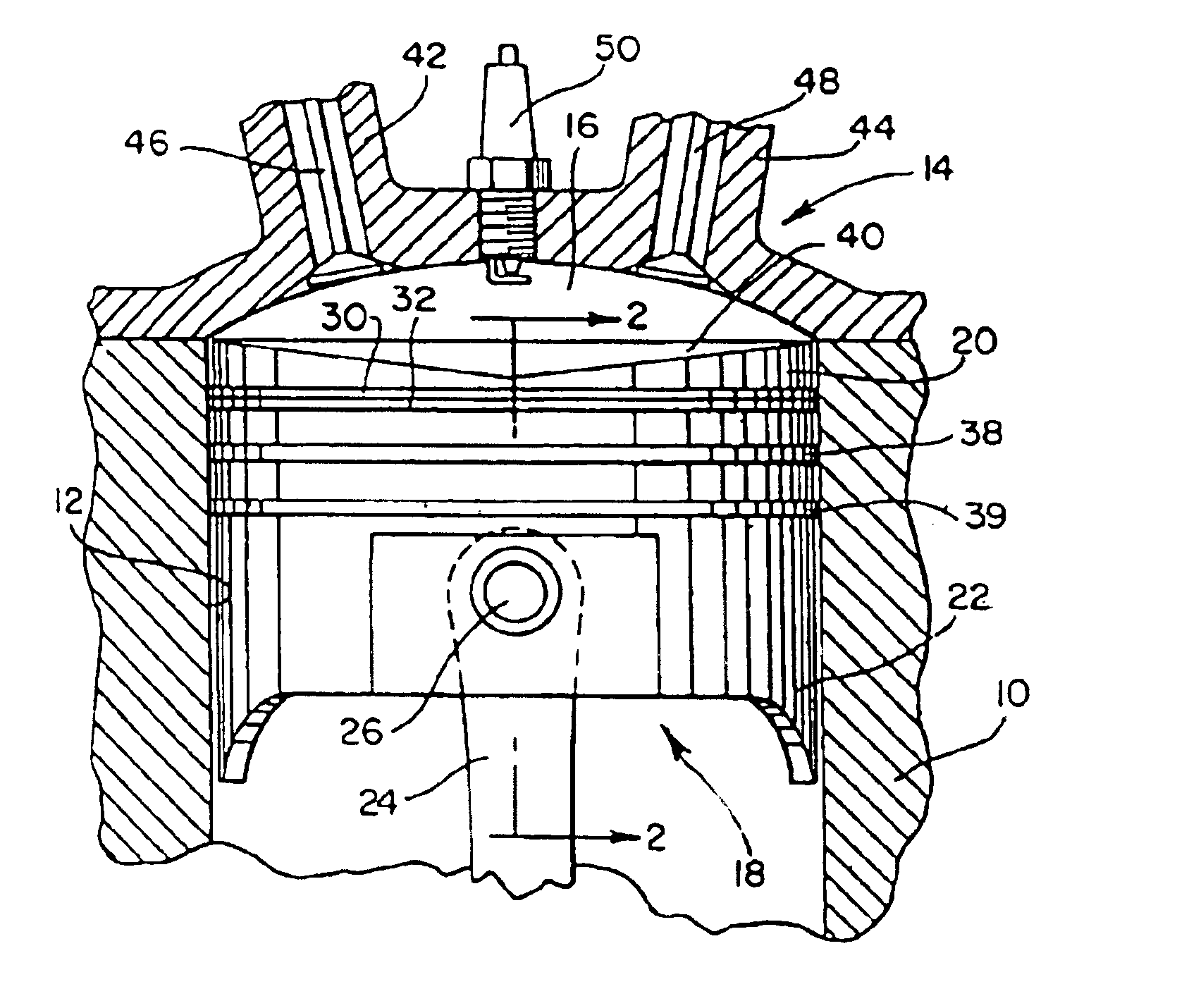
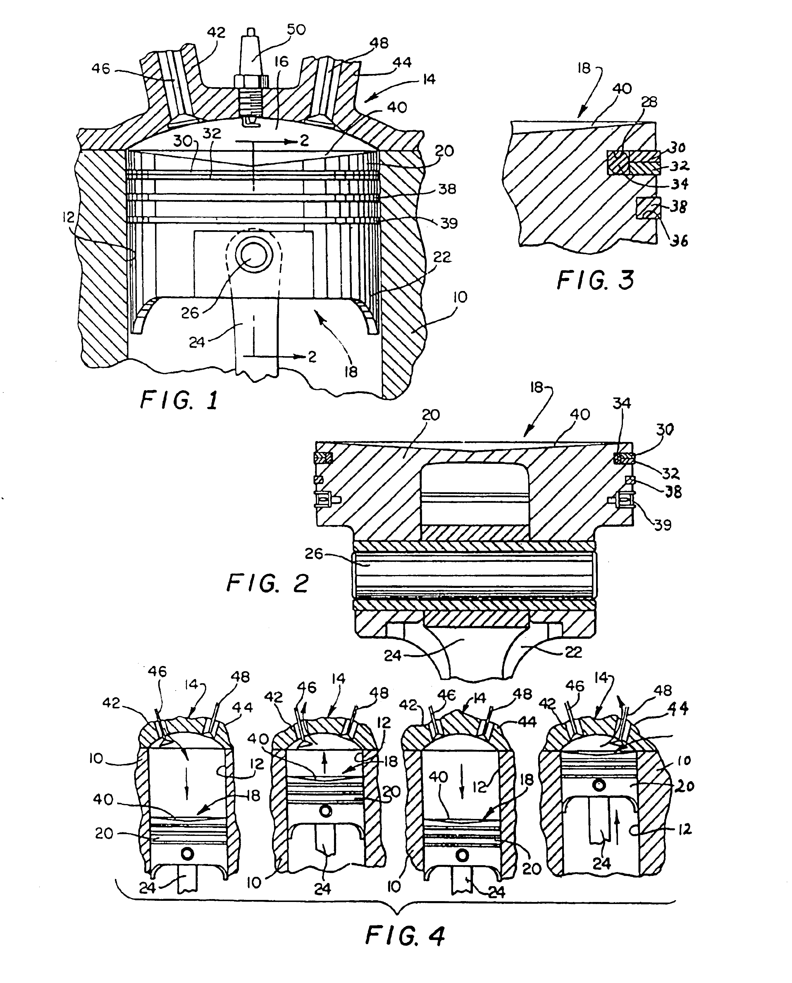
One of the essential features embodied in the present invention is the replacement of conventional gapped metallic compression rings as used with the piston with either a combination of a non-metallic ring and a metallic ring or just a non-metallic ring. The sealing can be accomplished with one or more of the rings as disposed in the annular grooves or lands formed in the engine piston and it is contemplated that no more than two compression rings as received in the appropriately formed lands would be utilized. The oil rings that are normally utilized in piston constructions in internal combustion engines remain as a conventional part of the piston of the subject invention.

Referring now to the drawing and particularly to FIGS. 1-3, a portion of an engine construction as embodied in the subject invention is illustrated, the engine block being indicated at 10. It is understood that the block 10 is only representative of a conventional construction and that the complete block will be f...


PUM


Abstract

An internal combustion engine is disclosed that includes a piston construction having a compression ring sealing arrangement that prevents penetration of gases thereby, which gases normally produce pollution and inefficiency in gasoline consumption. The essential elimination of combustion gases and oil vapors from leaking through the compression rings effectively eliminates objectionable emissions that result in pollution and enables the vehicle in which the present invention is utilized to substantially increase its gasoline consumption efficiency; and in addition an engine incorporating the invention maintains its power output even while substantially increasing gasoline consumption efficiency.

Description

BACKGROUND OF THE INVENTIONIn the operation of internal combustion engines as located in the present day automotive vehicle, the engine is not only considered to be inefficient in the use of fuel but further is objectionable because of the emission of pollutants to atmosphere. Inefficient fuel consumption is known to be caused by incomplete combustion due to improper atomization of the fuel molecules and the improper mixture of oil vapors and prior combustion products with air-fuel mixture in the combustion chamber. In these prior known internal combustion engines, gases resulting from combustion leak behind the compression rings and are drawn therebelow into the crankcase of the engine. These gases in the form of vapors and as mixed with oil vapors are returned through the compression rings into the combustion chamber during the various cycles of the engine. This so-called “blow-by” of the gases and vapors through the compression rings normally results because of faulty sealing of ...

Claims


Application Information

Patent Timeline
IPC IPC(8): F16J9/06F16J9/00
CPCF16J9/06
Inventor CHIPPERFIELD, RICHARD F.
Owner RICH IDEAS CREATED - HLDG
Features
  • Generate Ideas
  • Intellectual Property
  • Life Sciences
  • Materials
  • Tech Scout
  • Unparalleled Data Quality
  • Higher Quality Content
  • 60% Fewer Hallucinations
Learn More