

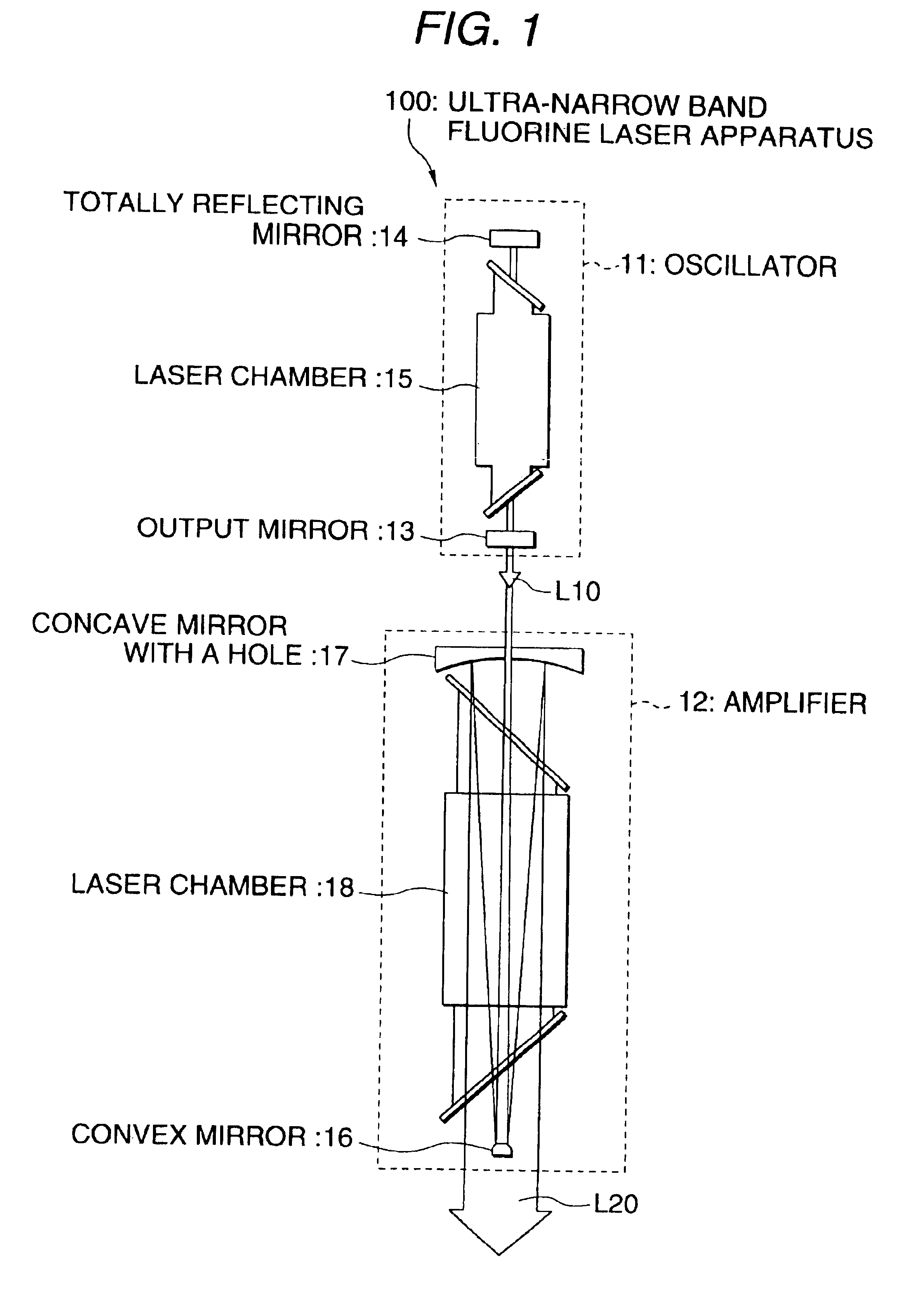
Ultra-narrow band flourine laser apparatus
a fluorine laser and narrow band technology, applied in the direction of optical resonator shape and construction, manufacturing tools, active medium materials, etc., can solve the problems of reducing the bandwidth of the fluorine laser oscillation beam, reducing the efficiency of the laser, and reducing the difficulty of achieving surface accuracy /100. , to achieve the effect of preventing the leakage of fluorine gas, simplifying the laser apparatus, and reducing the bandwidth of the fluorine gas
- Summary
- Abstract
- Description
- Claims
- Application Information
AI Technical Summary
Benefits of technology
Problems solved by technology
Method used
Image

Examples
second embodiment
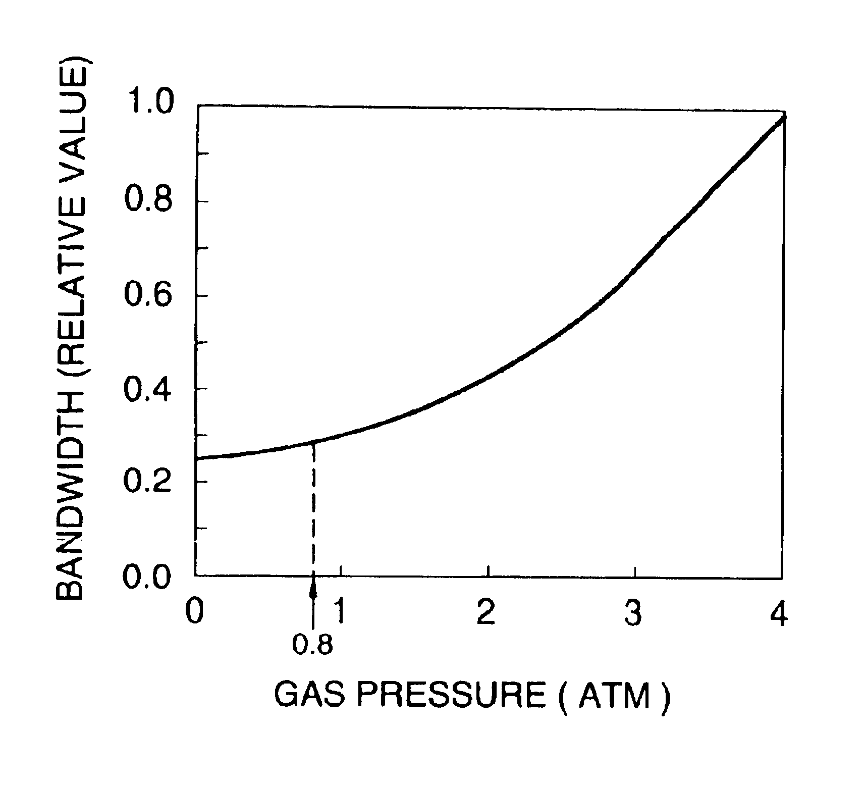
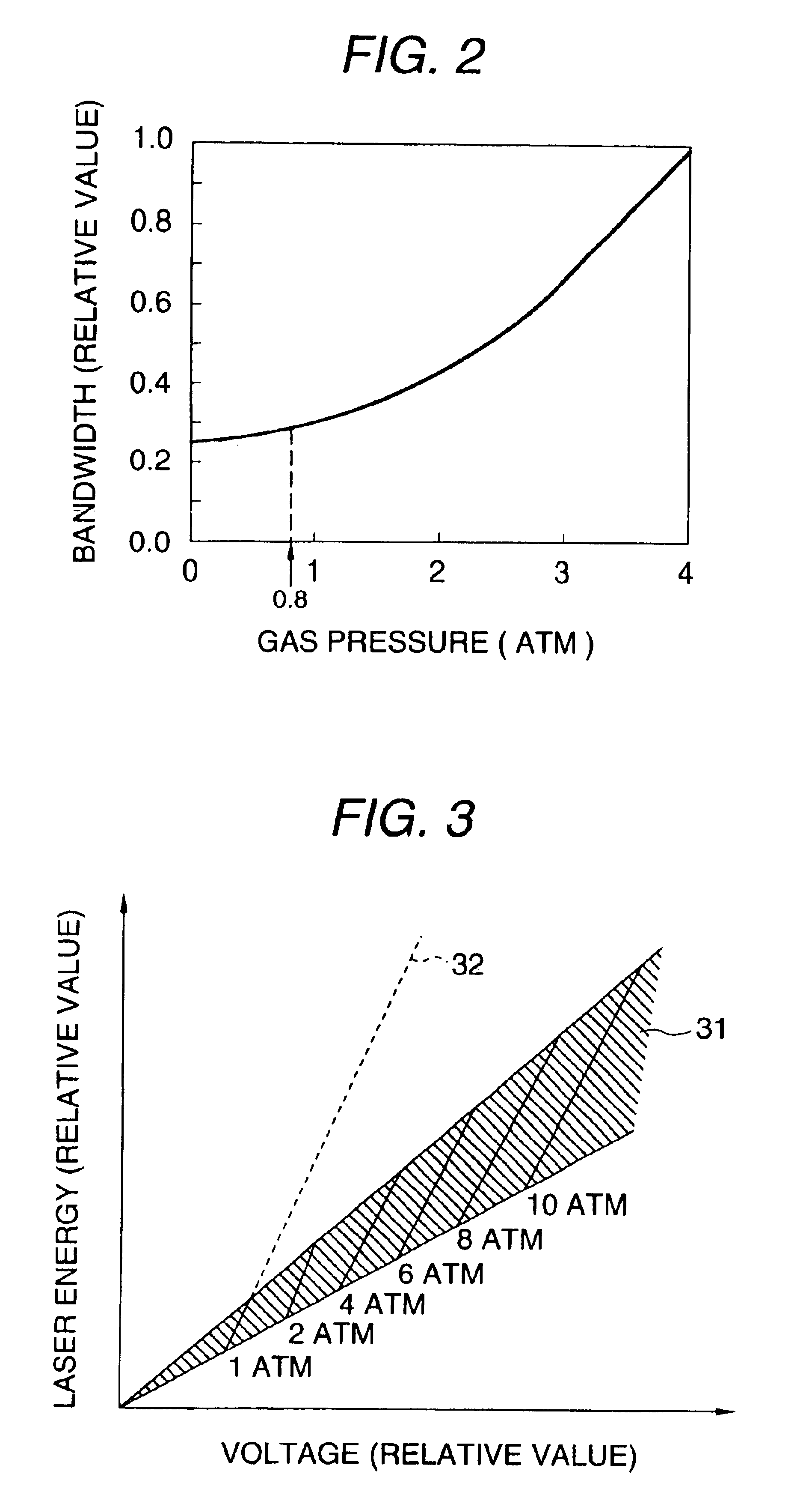
The second embodiment is the same as the first embodiment in that a fluorine laser is operated with the total pressure (hereinafter referred to as “gas pressure”) of the laser gas kept at 1 atm or less to generate laser light with a bandwidth narrowed to about 0.3 pm.
The present embodiment employs the longitudinal excitation system to be detailed later unlike the first embodiment which employs the transverse excitation system. By employing the longitudinal excitation system, a long interval is set between the cathode and anode in the laser chamber without decreasing the discharge voltage to be applied between the electrodes when the gas pressure is decreased, thereby suppressing the occurrence of arc discharge between those electrodes.
As shown in FIG. 4, the ultra-narrow band fluorine laser apparatus 200 has a stable resonator which is a resonator constituted by an output mirror 21 and a totally reflecting mirror 22 containing a laser chamber 23. The laser apparatus has the same con...
third embodiment
the invention will now be described.
FIG. 5 is an illustration of a configuration of a fluorine exposure tool 300 utilizing an ultra-narrow band fluorine laser apparatus.
The fluorine exposure tool 300 is generally constituted by an ultra-narrow band fluorine laser apparatus 100 as shown in FIG. 1 and an exposure tool main body 110.
The exposure tool main body 110 is provided on a grating 41 in a clean room, and the ultra-narrow band fluorine laser apparatus 100 is provided on a floor 42 (a floor generally referred to as “under floor”) under the grating 41.
Laser light L20 having only intense lines (oscillation beams) in a bandwidth of about 0.3 pm provided by the ultra-narrow band fluorine laser apparatus 100 travels upward after being reflected by a mirror 43a, passes through an aperture 44 of the grating 41 and enters the exposure tool main body 110.
The laser light L20 travels in a glass rod 46 made of calcium fluoride after being converged by a lens 45. The light is subjected repeat...
PUM
| Property | Measurement | Unit |
|---|---|---|
| pressure | aaaaa | aaaaa |
| total pressure | aaaaa | aaaaa |
| pressure | aaaaa | aaaaa |
Abstract
Description
Claims
Application Information