Planar capacitive transducer

a capacitive transducer and capacitive technology, applied in the direction of resistance/reactance/impedence, instruments, mechanical means, etc., can solve the problems of loss of calibration, slow response, sensitivity reduction, etc., and achieve the effect of increasing or decreasing surface free energy

Inactive Publication Date: 2005-01-11
MCINTOSH ROBERT B
View PDF7 Cites 37 Cited by
  • Summary
  • Abstract
  • Description
  • Claims
  • Application Information

AI Technical Summary

Benefits of technology

Still another embodiment of the present invention includes a capacitive transducer with a principal surface that is activated to increase or decrease surface free energy. Specific applications of economic importance for the transducers of the present invention include, but are not limited to:1. Improved chemically resistant transducers to measure the moisture content of bulk stored agricultural and industrial products; to control milling, drying, and baking systems; and to control mois

Problems solved by technology

A disadvantage of these sensors is a slow response due to a time required for bulk material to reach equilibrium with water vapor in an external environment.
Other disadvantages are a loss of calibration, reduction of sensitivity, and failure due to material absorption and surface retention of contaminants including fluids and particulates.
However, this approach further constrains sensor response time and does not provide a capability for reliable operation in an environment of fine airborne particul

Method used


Image

  • Planar capacitive transducer
  • Planar capacitive transducer
  • Planar capacitive transducer

Examples


Embodiment Construction

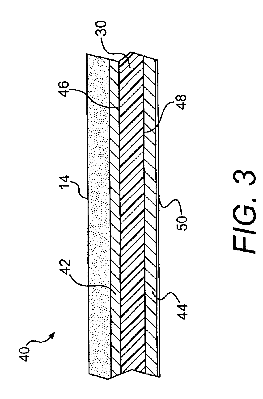
FIG. 4A is a top view of first metal layer 42 of capacitor 40 of FIG. 3. Capacitor electrodes generally shown by reference numeral 54 comprise interdigitated fingers etched in metal layer 42. A first planar capacitor electrode comprises a set of fingers 56 connected to a ground bus 58 connected to a wire point pad 60 with a plated through hole 60′. A cooperating capacitor electrode comprises a second set of fingers 62 connected to a sensing bus 64 connected to a wire point pad 66 with a plated through hole 66′. Capacitor 40 is measured by connecting capacitance measurement electronics means between pads 60 and 66. A third wire point pad 68 with a plated through hole 68′ is used to connect an electrical signal to a driven shield 70 etched in a second metal layer 44 shown in FIG. 4B. Capacitor 40 is die-cut to dimensions defined by registration marks 72. The width and spacing of fingers 56 and 62 for flexible circuit embodiments of the transducer can range between 0.001 and 0.006 inch...


PUM


Abstract

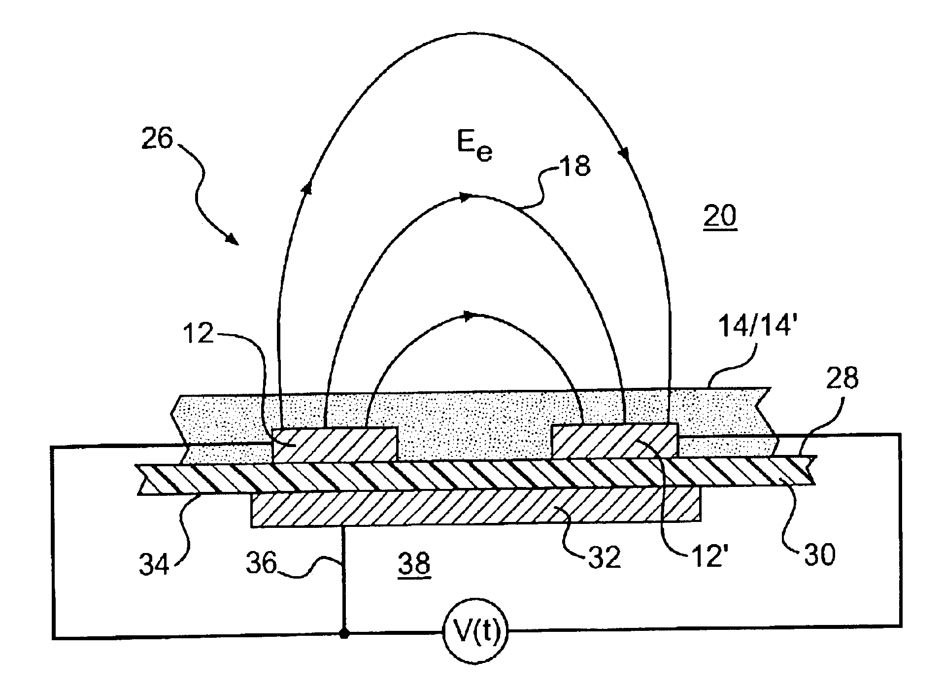
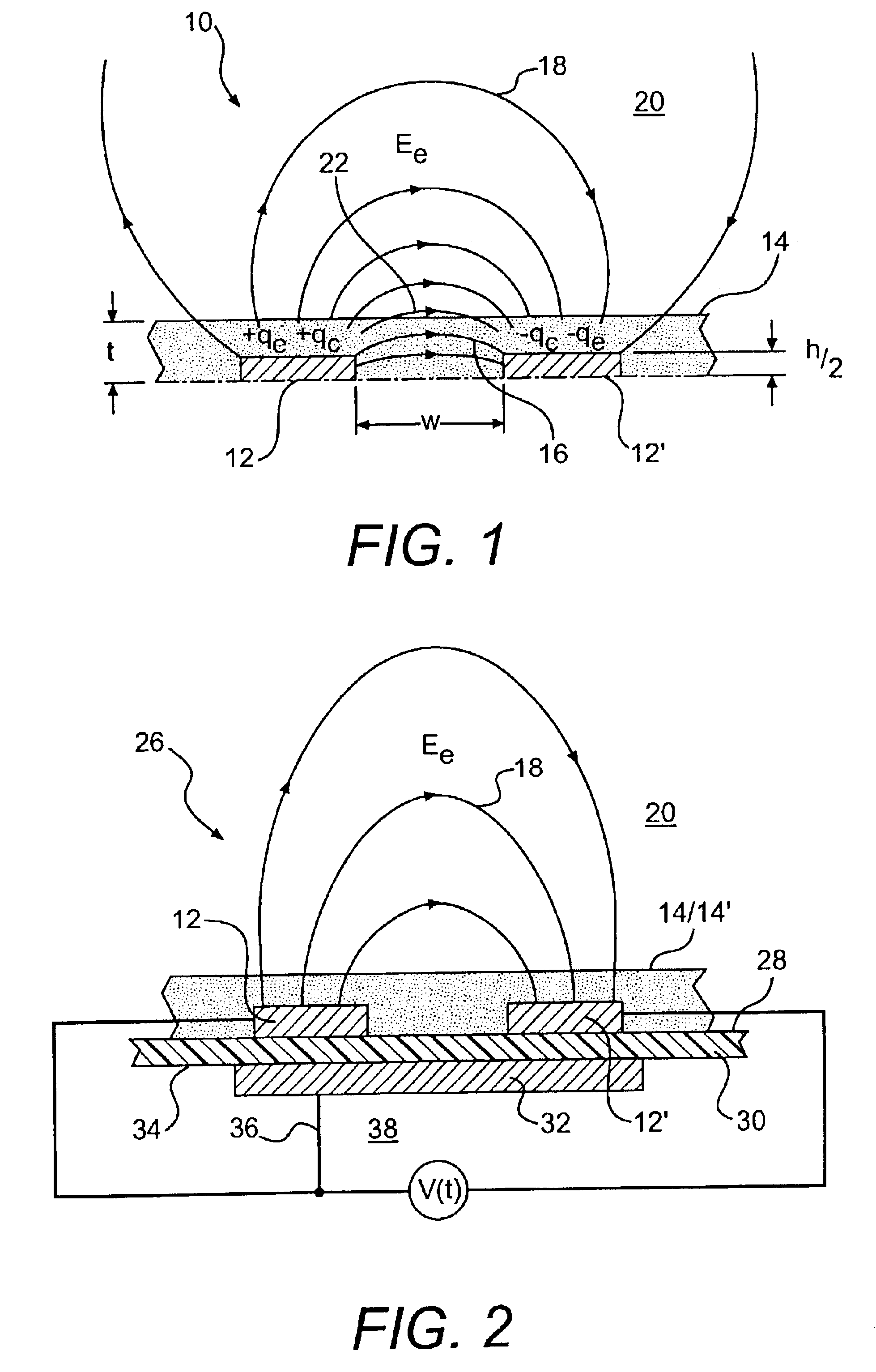
A transducer comprising at least one planar capacitor with a thin coverlayer of material selected to maximize electric field coupling between cooperating capacitor electrodes within a region external to a principal surface of the coverlayer. Preferred coverlayer materials have low values of moisture absorption, surface free energy, permittivity, dielectric dissipation, and electrical conductance. According to one embodiment of the invention, a driven shield further enhances electric field coupling over and in a region external to the principal surface. The transducer also can promote a physical change in specific adsorbates and materials and simultaneously detect and measure an effect of the induced change. Applications for the transducer of the invention include the measurement of the moisture content of grain and bulk stored commodities, humidity, a dew point temperature, the onset of condensation and rates of adsorption and desorption.

Description

FIELD OF THE INVENTIONThe present invention relates to capacitance transducers that measure moisture, humidity, permittivity, dielectric dissipation, and states of electrical polarization of materials absorbed on and residing within a region external to a principal surface.BACKGROUND OF THE INVENTIONPrior-art capacitive moisture and humidity sensors detect a change in capacitance due to a change in permittivity of a porous material layer due to cyclic absorption and desorption of water vapor. A disadvantage of these sensors is a slow response due to a time required for bulk material to reach equilibrium with water vapor in an external environment. Accordingly, the design of existing electrical hygrometers is constrained by a trade off between sensitivity and acceptable response time. Other disadvantages are a loss of calibration, reduction of sensitivity, and failure due to material absorption and surface retention of contaminants including fluids and particulates.U.S. Pat. No. 6,22...

Claims


Application Information

Patent Timeline
IPC IPC(8): G01N27/22G01D5/24G01D5/12
CPCG01N27/223G01D5/2405
Inventor MCINTOSH, ROBERT B.
Owner MCINTOSH ROBERT B
Why Eureka
Try Eureka