Double-resonance-absorption microscope
a double-resonance absorption and microscope technology, applied in the field of double-resonance absorption microscopes, can solve the problems of inability to theoretically expect, inability to accurately identify the chemical composition of a sample, and the need for a higher spatial resolution, so as to achieve excellent operability and maintainability, excellent three-dimensional spatial resolution, and high s/n ratio
- Summary
- Abstract
- Description
- Claims
- Application Information
AI Technical Summary
Benefits of technology
Problems solved by technology
Method used
Image
Examples
example 1
FIG. 13 is a schematic diagram of one example of the double-resonance-absorption microscope in accordance with the present invention. The illustrated double-resonance-absorption microscope forms a laser-scanning fluorescence microscope, and is a system for focusing pump light and erase light into spots, detecting fluorescence while scanning a sample 1523 and the spots relative to each other, and imaging the fluorescence signal using a computer 1501.
The whole system is controlled by the computer 1501, which controls the timing of lasing of an Nd:YAG laser 1505 that is a fundamental light source via a laser controller 1502. At the same time, the computer controls movement of a sample stage 1524 via a sample stage controller 1503 in synchronism with the timing of lasing of the laser to scan the sample 1523 in two dimensions. Concurrently, the fluorescence signal from the sample 1523 is taken from an ICCD camera 1540 via a camera controller 1504 in synchronism with the lasing of the las...
example 2
FIG. 24 is a schematic diagram showing one example of the double-resonance-absorption microscope in accordance with the present invention. The illustrated microscope forms a laser scanning fluorescence microscope. Pump light and erase light are focused into spots. Fluorescence is detected while scanning a sample 2523 relative to the spots. The detected fluorescence signal is imaged using a computer 2501.
The whole system is controlled by the computer 2501, which controls the timing of lasing of an Nd:YAG laser 2505 that is a fundamental light source via a laser controller 2502. At the same time, the computer controls movement of a sample stage 2524 via a sample stage controller 2503 in synchronism with the timing of lasing of the laser to scan the sample 2523 in two dimensions. Concurrently, the fluorescence signal from the sample 2523 is taken from an ICCD camera 2540 via a camera controller 2504 in synchronism with the lasing of the laser.
In the present embodiment, it is assumed th...
example 3
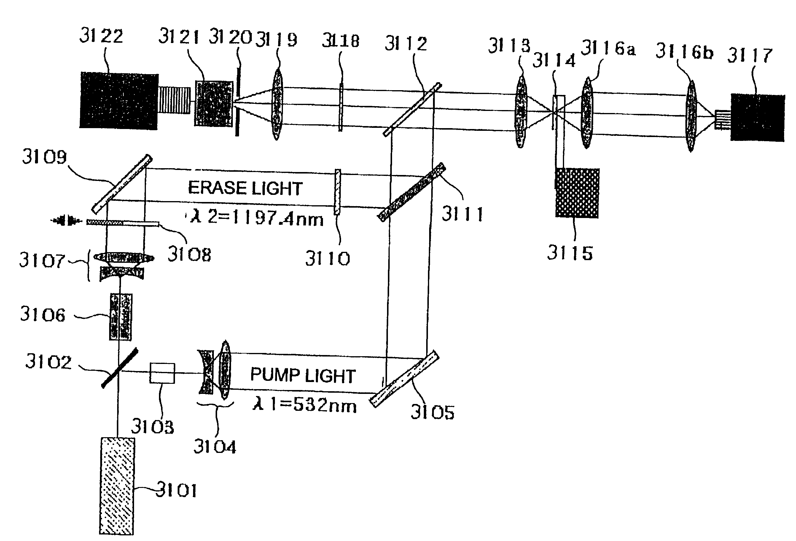
FIG. 30 is a schematic diagram showing one example of the solid-state dye laser in accordance with the present invention. This laser is capable of wavelength conversion.
The solid-state dye laser shown in FIG. 30 includes a solid laser medium 2703 having a pumping surface. A prism 2705 is placed in intimate contact with the pumping surface. In this geometry, if dye-pumped light 2702 from a short pulsed laser 2701 acting as an excitation light source is made to hit the pumping surface of the solid-state laser medium 2703 at an angle, the transmitted light and the light reflected inside the prism directly interfere with each other at the boundary surface between the prism 2705 and the solid laser medium 2703. This creates a periodic inverted distribution within the solid laser medium 2703 at the pitch of interference fringes 2706. At this time, if the wavelength of the standing wave within the solid laser medium 2703 satisfies the Bragg condition determined by the pitch of the inverted...
PUM
 Abstract
Description
Claims
Application Information
 - R&D
- Intellectual Property
- Life Sciences
- Materials
- Tech Scout
- Unparalleled Data Quality
- Higher Quality Content
- 60% Fewer Hallucinations
Browse by: Latest US Patents, China's latest patents, Technical Efficacy Thesaurus, Application Domain, Technology Topic, Popular Technical Reports.
© 2025 PatSnap. All rights reserved.Legal|Privacy policy|Modern Slavery Act Transparency Statement|Sitemap|About US| Contact US: help@patsnap.com


