Photomask having an intermediate inspection film layer

a technology of inspection film and photomask, which is applied in the direction of photomechanical equipment, instruments, and photosensitive materials, can solve the problems of affecting defects in the geometry of pattern design, and unwanted clear areas, so as to improve the inspection of all features

Inactive Publication Date: 2005-02-15
PHOTRONICS INC
View PDF28 Cites 12 Cited by
  • Summary
  • Abstract
  • Description
  • Claims
  • Application Information

AI Technical Summary

Benefits of technology

Unlike the prior art, the present invention teaches the deposition of one or more thin films during the manufacture of the photomask blank to ensure that the entire film stack is visible at a key inspection wavelength. These thin film(s) are made from materials which improve the inspectibility of all features on the photomask before they are even patterned.

Problems solved by technology

The phase-shifted electric field amplitude and the non-phase-shifted electric field amplitude destructively interfere with each other.
A defect is any flaw affecting the geometry of the pattern design.
For example, a defect may result when chrome is located on portions of the EAPSM 10 where it should not be (e.g., chrome spots, chrome extensions, or chrome bridging between geometry) or unwanted clear areas (e.g., pin holes, clear extensions, or dear breaks).
A defect in an EAPSM can cause a semiconductor to function improperly.
If such defects cannot be repaired, the mask must be rejected and rewritten.
Current inspection tools, however, are often unable to detect defects in conventional EAPSMs.
These same phase shift materials, by contrast, are highly transmissive at the greater, inspection tool wavelength (currently 365 nm), thereby making it difficult for inspection tools to detect defects in the EAPSM during inspection.
This is required so that the inspection tools can distinguish between light and dark areas on the EAPSM, thereby making defects apparent to the inspection tool.
Phrased another way, the inspection tool is unable to distinguish between light and dark areas in the mask.
Thus, it has become increasingly difficult to obtain reliable and accurate inspection results.
As a result, the reliability of inspection equipment has become increasingly marginal.
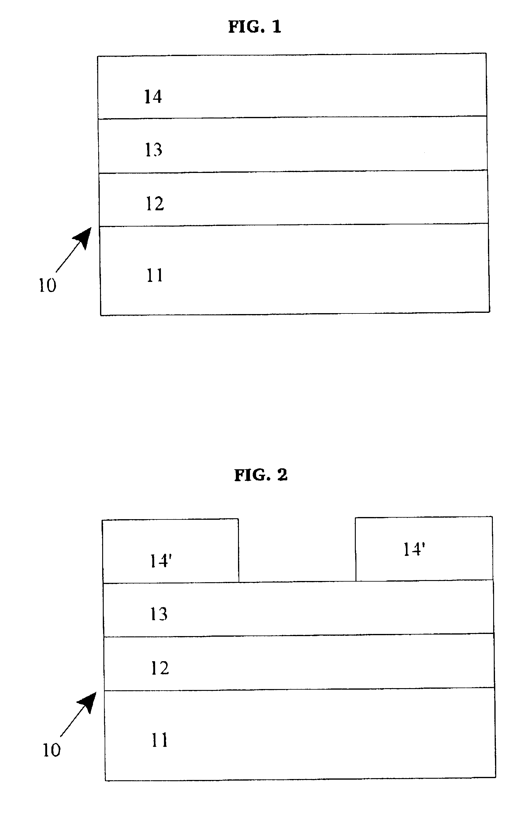
Because transmission here is outside the acceptable optical range required by current inspection tools (e.g., 40-50% or less), the inspection tool cannot adequately distinguish the TaSiN PSM layer 12 from the quartz layer.
As a result, defects in the photomask are not detected, and thus, the semiconductor from which the mask will be made (once the mask is etched or processed) may have imperfections.
Accordingly, reliable inspection results cannot be obtained.
After inspection is completed (albeit with unsatisfactory results), a completed photomask is cleaned of contaminants.
The cleansing process can also affect the quality of the photomask.
Inspection tool manufacturers lag behind the wafer stepper manufacturers and have not modified their inspection equipment to meet the optical properties of current EAPSMs.
Thus, current phase shift materials meet the optical requirements of exposure tool wavelength (e.g. 193 nm, 157 nm and 247 nm), on the one hand, but do not meet the optical requirements of inspection tool wavelength (e.g., 365 nm), on the other hand.
Other prior art discloses methods for improving the overall inspection of photomasks, however, this prior art does not address the particular need to make defects in current EAPSMs inspectible in the first instance.
Although useful in improving the inspection of photomasks, this method has some significant drawbacks in its operation and results.
As a result, the overall productivity of a photomask production facility is decreased.
Additionally, by depositing the contrast enhancing layer to the photomask after it has been processed, there is an added risk that the photomask will incur additional defects during the deposition of such layer on the photomask.
Further, the O'Grady Patent does not address the problem associated with inspection equipment as discussed herein.
Specifically, the O'Grady Patent does not disclose the selection of materials for the contrast enhancing layer which will decrease the transmission of light through the PSM layer of an EAPSM to approximately 40-50% or less when compared with transmission through the quartz region of the EAPSM, as required by current inspection tools.
Thus, although useful in enhancing the size of defects during inspection, such defects may not be detected in the first instance using the mask of the O'Grady Patent.
Accordingly, poor inspection results are still obtained using the photomask of the O'Grady Patent.
However, the Toppan Patents do not address the problem of obtaining reliable inspection results for EAPSMs (e.g., MoSi based materials) which are more typically used in the semiconductor industry.
In this regard, zirconium-based half tone masks are rarely used since as zirconium has been found to exhibit poor etching properties.
Thus, the teachings of the Toppan Patents are limited to zirconium-based half tone masks and do not address the problems associated with inspecting EAPSMs more commonly used in the semiconductor industry.

Method used


Image

  • Photomask having an intermediate inspection film layer
  • Photomask having an intermediate inspection film layer
  • Photomask having an intermediate inspection film layer

Examples


example

An EAPSM was made to have a chromium intermediate layer deposited beneath a silicon nitride PSM layer. More particularly and as shown in FIG. 7A, the EAPSM 21 includes quartz as the transparent layer 31, non-stoichiometric chromium nitride as the intermediate layer 29 having a thickness of 115 Å, silicon nitride (e.g., Si3N4) as the PSM layer 27 having a thickness of 674 Å, chromium as the opaque layer 25 and a photoresist layer 23. The silicon nitride PSM layer 27 was tuned for 193 nm exposure tools and 365 nm inspection tools. Referring to FIG. 12, it was found that the EAPSM 21 transmitted light at a rate of 9% with a 180 degree phase shift at the 193 nm exposure tool wavelength. At the 365 nm inspection tool wavelength, the EAPSM 21 transmitted light at a rate of approximately 35%. As a result, the EAPSM was able to meet the optical requirements of both inspection and exposure tools.

It is noted that the present invention is not limited to the specified exposure and inspection to...


PUM

PropertyMeasurementUnit
thicknessaaaaaaaaaa
thicknessaaaaaaaaaa
thicknessaaaaaaaaaa

Abstract

The present invention relates generally to improved photomask blanks used in photolithography for the manufacture of integrated circuits and other semiconductor devices, and more specifically, to the detection of defects in such photomasks after processing. In particular, the present invention is directed to a photomask blank having one or more intermediate layers made from materials having a higher extinction coefficient at the inspection tool wavelength than exposure tool wavelengths. The intermediate layer(s) are made from materials that absorb a sufficient amount of light to meet the optical requirements of inspection tools while at the same time transmit a sufficient amount of light to meet the optical requirements of exposure tools. As a result, the photomask improves inspection results of a photomask without sacrificing transmission properties during the semiconductor writing process.

Description

FIELD OF THE INVENTIONThe present invention relates generally to an improved photomask used in photolithography for the manufacture of integrated circuits and other semiconductor devices, and more specifically, to the detection of defects in such photomasks after processing. In particular, the present invention is directed to a photomask, either blank or processed, having one or more intermediate layers deposited therein to improve inspection results of the photomask without sacrificing transmission properties at the exposure tool wavelength. Additionally, the present invention is directed to semiconductors or other integrated circuits manufactured using the improved photomask of the present invention.BACKGROUND OF THE INVENTIONPhotomasks are high precision plates containing microscopic images of electronic circuits. Photomasks are typically made from flat pieces of quartz or glass with a layer of chrome on one side. Etched in the chrome is a portion of an electronic circuit design,...

Claims


Application Information

Patent Timeline
Patent Type & Authority Patents(United States)
IPC IPC(8): G03F1/00G03F1/08G03F1/32G03F1/38G03F1/54G03F1/84H01L21/027
CPCG03F1/32G03F1/84G03F1/54G03F1/38
Inventor LASSITER, MATTHEWCANGEMI, MICHAEL
Owner PHOTRONICS INC
Why Eureka
Try Eureka