Lithographic method and apparatus

a technology of lithographic exposure and lithographic method, which is applied in the direction of printers, photo-taking processes, photographic processes, etc., can solve the problems of increasing the density of features, increasing the demand for ever-smaller features, and proving expensive, so as to reduce the size of features

Inactive Publication Date: 2005-02-15
ASML NETHERLANDS BV
View PDF69 Cites 83 Cited by
  • Summary
  • Abstract
  • Description
  • Claims
  • Application Information

AI Technical Summary

Benefits of technology

The method of the invention enables lithography to be performed with reduced feature size and / or improved processing parameters such as exposure latitude, Mask Error Factor (MEF), depth of focus and proximity effects, without having to use improved optics and / or diffraction-assisted masks.

Problems solved by technology

Problems with the prior art include that in the semiconductor manufacturing industry there is increasing demand for ever-smaller features and increased density of features.
However, none of these methods is entirely satisfactory and they can also prove expensive.

Method used


Image

  • Lithographic method and apparatus
  • Lithographic method and apparatus
  • Lithographic method and apparatus

Examples


embodiment 1

In optical lithography it is known to use off-axis illumination, which enables smaller features to be successfully imaged. With this technique, the mask is illuminated at non-perpendicular angles, which in particular improves the process latitude by increasing the depth of focus and / or contrast.

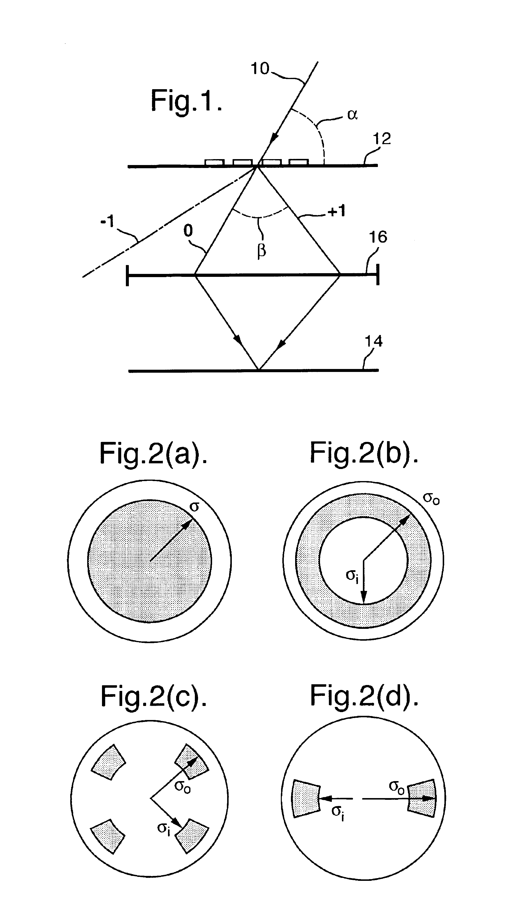
FIG. 1 illustrates this principle in which a beam of radiation 10 is incident on a mask 12 at an angle 90°-α inclined to the optical axis, which is conventionally vertical. The incident beam 10 is diffracted by the features on the mask 12 which are to be imaged on the wafer 14. The zeroth and two first-order-diffracted beams (0, ±1) are shown in FIG. 1. Improved performance can be achieved when, for example, at least part of the zeroth order and one of the first orders, which are coherent, are captured by the projection lens 16 and used to form the image on the wafer 14.

The smaller the pitch of features on the mask 12 the larger the diffraction angle β will be. If the size of the features dec...

embodiment 2

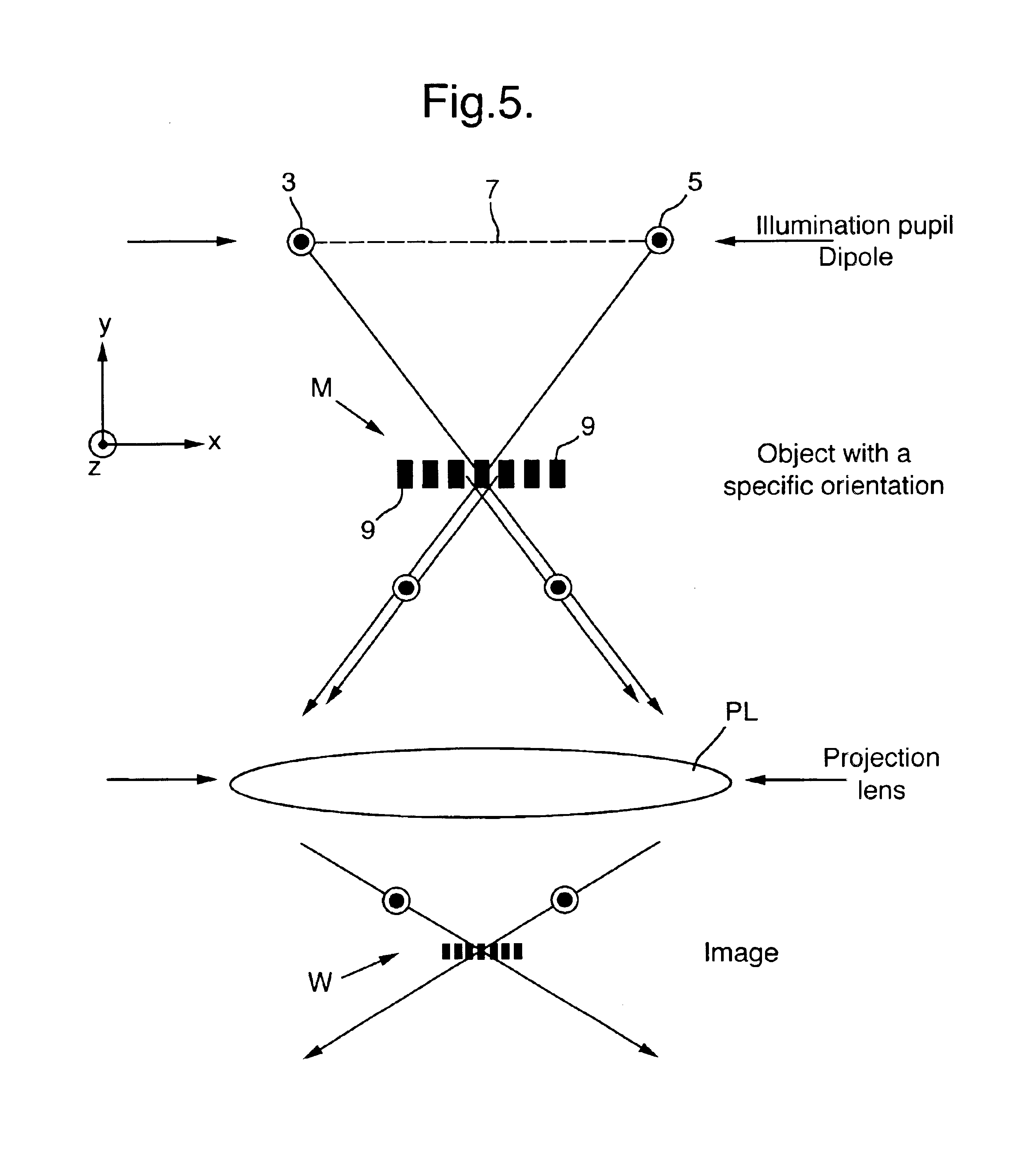
A preferred embodiment of the method of the invention is to perform two exposures using two respective perpendicular dipole patterns. The first exposure is used to image mask features parallel to a first direction, and the second exposure using the other dipole illumination mode is used to image mask features perpendicular to the first direction.

In one particular embodiment, two distinct masks are used, one for each of the exposures, and the superposition of the images of the two masks produces a single circuit pattern. As well as changing between mutually perpendicular dipolar illumination modes and changing masks between the first and second exposures it is possible to select independently the specific parameters of the dipole illumination mode for each exposure, such as σo and σi and so on, in order to optimize the exposure for the structure sizes parallel and perpendicular to the first direction.

In an alternative embodiment, a single mask is used, but the said mask contains two ...

embodiment 3

A further embodiment of the present invention is to use a “soft dipole” illumination mode for at least one of the dipole exposures. A soft dipole mode is particularly suited to imaging a pattern which includes some features which are not in the x or y directions; for example, diagonal or curved lines. Some examples of soft dipole illumination modes include a basic dipole intensity distribution as shown in FIG. 2(d) but with a weaker general background illumination across the pupil, or with a weaker central on-axis pole in addition to the two off-axis poles, or it may resemble a quadrupole illumination mode, but with two strong intensity poles and two weaker intensity poles.


PUM

PropertyMeasurementUnit
energy-sensitiveaaaaaaaaaa
sizeaaaaaaaaaa
electric fieldaaaaaaaaaa

Abstract

A method of imaging a pattern in a microlithographic exposure apparatus includes performing two exposures, each with a different mask, the superposition of the images defined by the two masks produces the complete circuit pattern. A dipolar illumination mode is used for each exposure, the dipoles of the two exposures being mutually perpendicular. The dipolar illumination mode of the first exposure is used to image mask features parallel to a first direction, and the dipolar illumination mode of the second exposure is used to image mask features perpendicular to the first direction.

Description

BACKGROUND OF THE INVENTION1. Field of the InventionThe present invention relates to a method and apparatus for microlithographic exposure, and more particularly, to the application of such a method in a lithographic projection apparatus.2. Discussion of Related ArtFor the sake of simplicity, the projection system may hereinafter be referred to as the “lens”; however, this term should be broadly interpreted as encompassing various types of projection system, including refractive optics, reflective optics, and catadioptric systems, for example. The radiation system may also include elements operating according to any of these principles for directing, shaping or controlling the projection beam of radiation, and such elements may also be referred to below, collectively or singularly, as a “lens”. In addition, the first and second object tables may be referred to as the “mask table” and the “substrate table”, respectively. Further, the lithographic apparatus may be of a type having two...

Claims


Application Information

Patent Timeline
Patent Type & Authority Patents(United States)
IPC IPC(8): G03F7/20G03F1/08H01L21/027
CPCG03F7/70425G03F7/70125H01L21/027
Inventor FINDERS, JOZEF MBASELMANS, JOHANNES JFLAGELLO, DONIS GBOUCHOMS, IGOR P
Owner ASML NETHERLANDS BV
Why Eureka
Try Eureka