Near-field transform spectroscopy

a near-field transform and spectroscopy technology, applied in the field of chromatography, can solve the problems of inability to demonstrate sub-wavelength imaging using nf light, inability to achieve spectroscopic resolution enhancement, the effect of improving the signal-to-nois

Inactive Publication Date: 2005-02-22
GOOGLE TECH HLDG LLC
View PDF11 Cites 51 Cited by
  • Summary
  • Abstract
  • Description
  • Claims
  • Application Information

AI Technical Summary

Benefits of technology

a data processor is disclosed. One advantage of the present invention includes the improvement of the signal-to-noise (e.g., S/N) ratio for spectroscopic measurements in order to achieve inter alia enhanced spectroscopic resolution. Additionally, the present invention also provides for increased sample throughput, with the utilization of multiplex detection and time-to-frequency transform methods, as well as single-molecule detection sensitivity. Other exemplary embodiments include detection systems and/or methods suitably adapted to employ apertureless NF generation.
In one representative aspect, a system is configured to transform time-domain signal input into frequency-domain output in order to achieve sub-diffraction-limited scale detection or imaging of analytes within a heterogeneous multi-component sample without requiring inter alia pre-conditioning of the initial starting conditions at the time of sample loading. Near-field transform spectroscopy also provides for a new regime of analyte-specific information by exploiting higher frequency information in the localized region of non-pro...

Problems solved by technology

In practical terms, these limitations have typically involved the wavelength of light used, which generally defines the minimum scale of effective measurement this despite the best efforts of lens makers to perfect or otherwise improve the optical art.
However, diffraction-imposed constraints are generally not unique to lithographic processes alone; analytical methods used in materials characterization studies (i.e., microscopies, polarization studies and various spectroscopic methods) also suffer from substantially similar limitations.
In general, all illuminated objects have both NF and FF components; however, most conventional spectroscopic methods generally avail themselves to diffraction-limited propagative components in the FF.
In 1928, Synge described but was not able to demonstrate sub-wavelength imaging using NF light.
In most cases, conventional FF mechanisms of optical cont...

Method used


Image

  • Near-field transform spectroscopy
  • Near-field transform spectroscopy
  • Near-field transform spectroscopy

Examples


Embodiment Construction

The following descriptions are of exemplary embodiments of the invention and the inventors' conceptions of the best mode and are not intended to limit the scope, applicability or configuration of the invention in any way. Rather, the following description is intended to provide convenient illustrations for implementing various embodiments of the invention. As will become apparent, changes may be made in the function and / or arrangement of any of the elements described in the disclosed exemplary embodiments without departing from the spirit and scope of the invention.

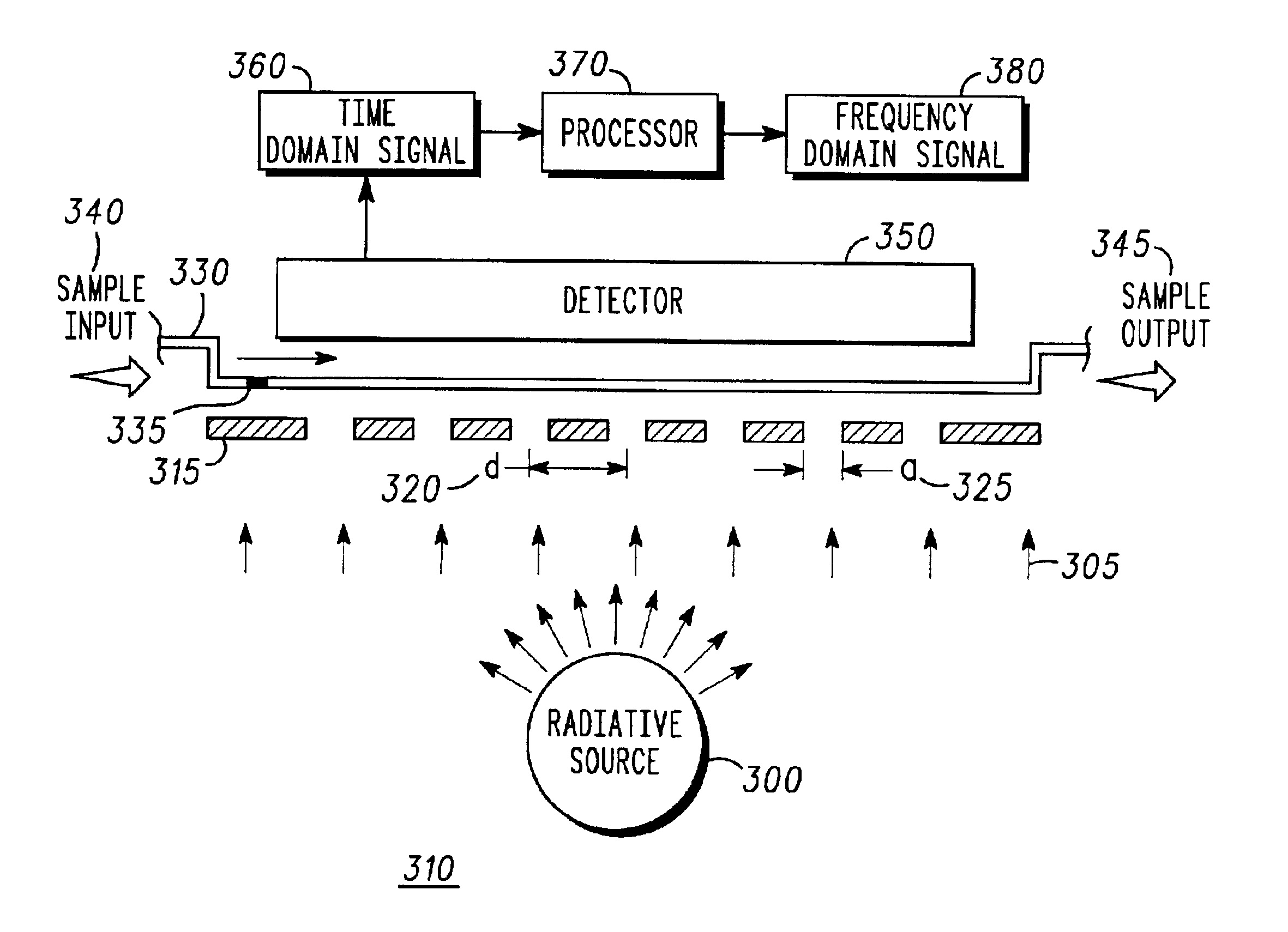
Various representative implementations of the present invention may be applied to any system and / or method for NF measurement and / or de-convolution of sub-diffraction-limited scale phenomena. Certain representative implementations may include, for example: the improvement of S / N in a NF detection or imaging system; the improvement of sample-throughput in a NF separation, excitation and / or detection system; and single mole...


PUM


Abstract

An exemplary system and method for detecting at least one analyte in a sample comprises inter alia a source of radiation (300), a near-field aperture array (315), a chromatographic field (330), a detector (350), and a data processor (370). Disclosed features and specifications may be variously controlled, adapted or otherwise optionally modified to improve detection of any sub-diffraction-limited scale phenomena. Exemplary embodiments of the present invention representatively provide for improved S/N, increased sample throughput, refined spectral resolution and enhanced detection sensitivity.

Description

FIELD OF INVENTIONThe present invention generally relates to spectroscopy and chromatography. More particularly, the present invention concerns a system and method for near-field transform detection of non-propagative evanescent phenomena.BACKGROUNDThe need to resolve objects smaller than those visible to the naked eye has existed from the beginning of observational science and natural philosophy. Since the 19th Century, the fundamental limitations of employing visible light to realize enhanced optical resolution, while unwelcome, have generally been well understood. In practical terms, these limitations have typically involved the wavelength of light used, which generally defines the minimum scale of effective measurement this despite the best efforts of lens makers to perfect or otherwise improve the optical art. Consequently, conventional light-optical methods have increasingly resorted to smaller wavelengths with the trend in semiconductor fabrication, for example, being toward ...

Claims


Application Information

Patent Timeline
IPC IPC(8): G01N30/74G01N30/00G01N21/55G01N30/86G01N30/60G01Q30/12G01Q60/18
CPCG01N21/552G01N21/648G01N30/74G01N30/44G01N30/6095G01N2030/6056G01N30/78G01N30/8617G01N30/8631
Inventor ZENHAUSERN, FREDERICCHOU, CHIA-FU
Owner GOOGLE TECH HLDG LLC
Why Eureka
Try Eureka