

Hydrostatic transaxles
a transaxle and hydrostatic technology, applied in the direction of fluid gearings, gearboxes, gearing control, etc., can solve the problems of increasing fluid leakage, and reducing the service life of the vehicl
- Summary
- Abstract
- Description
- Claims
- Application Information
AI Technical Summary
Benefits of technology
Problems solved by technology
Method used
Image

Examples
Embodiment Construction
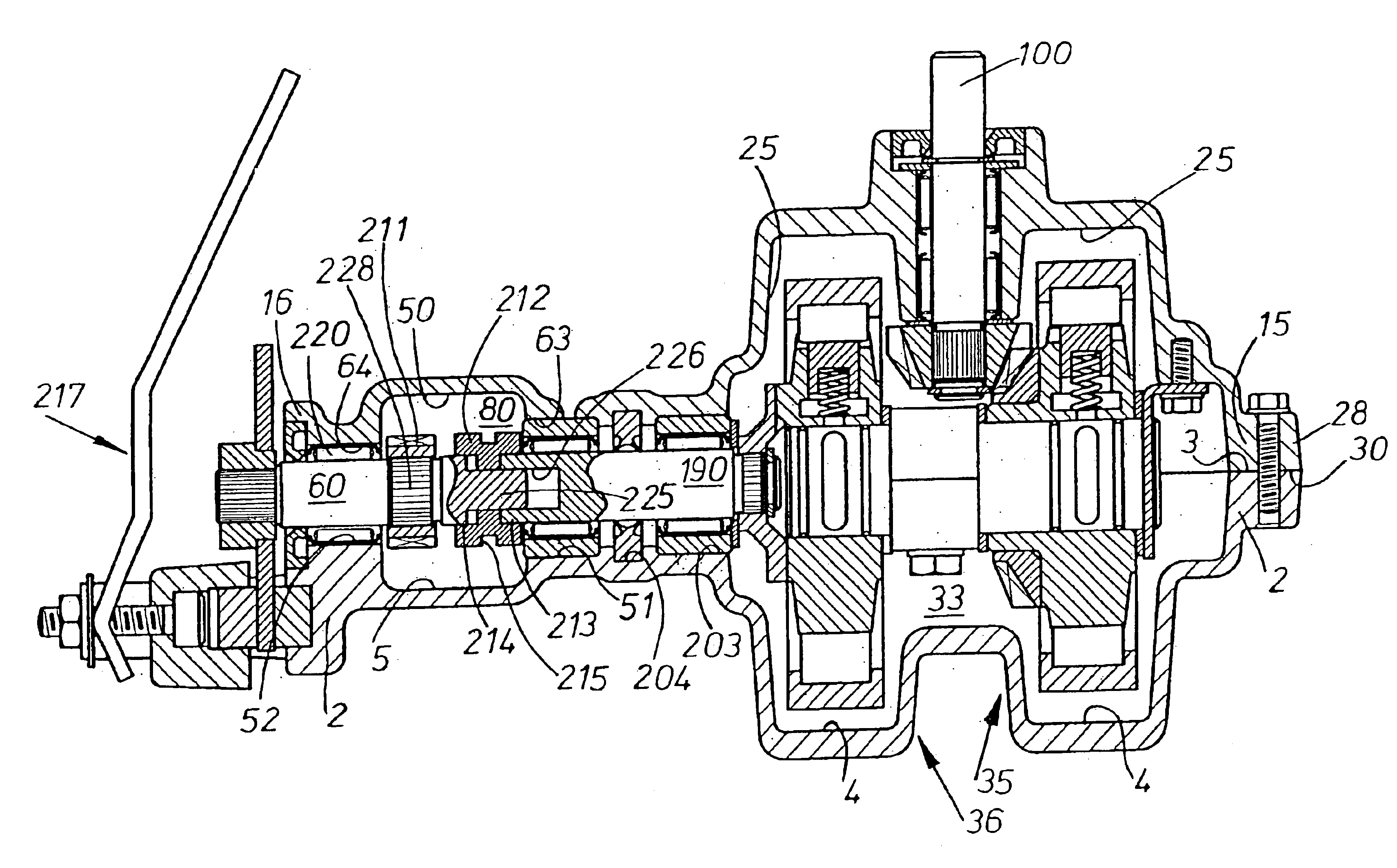
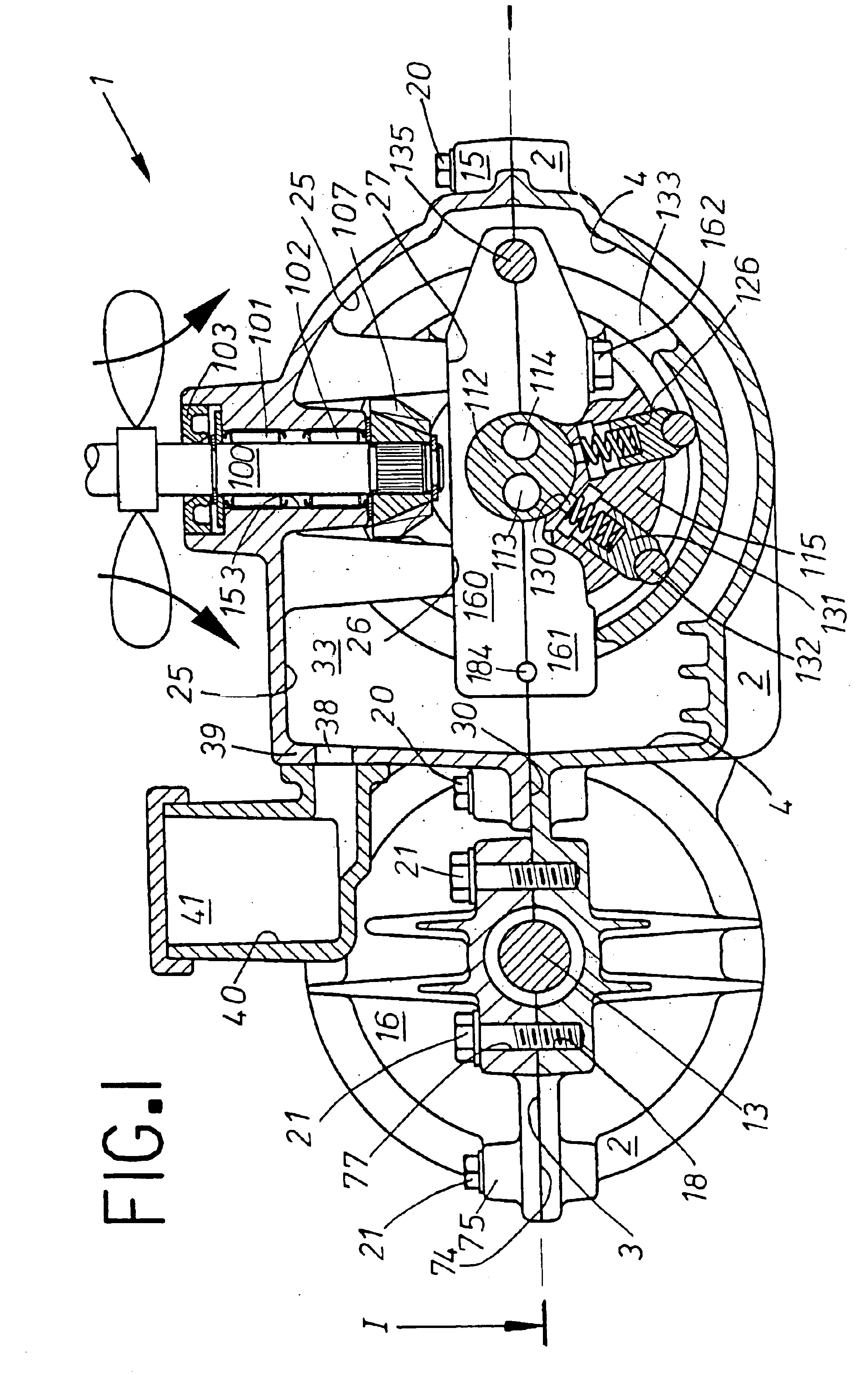
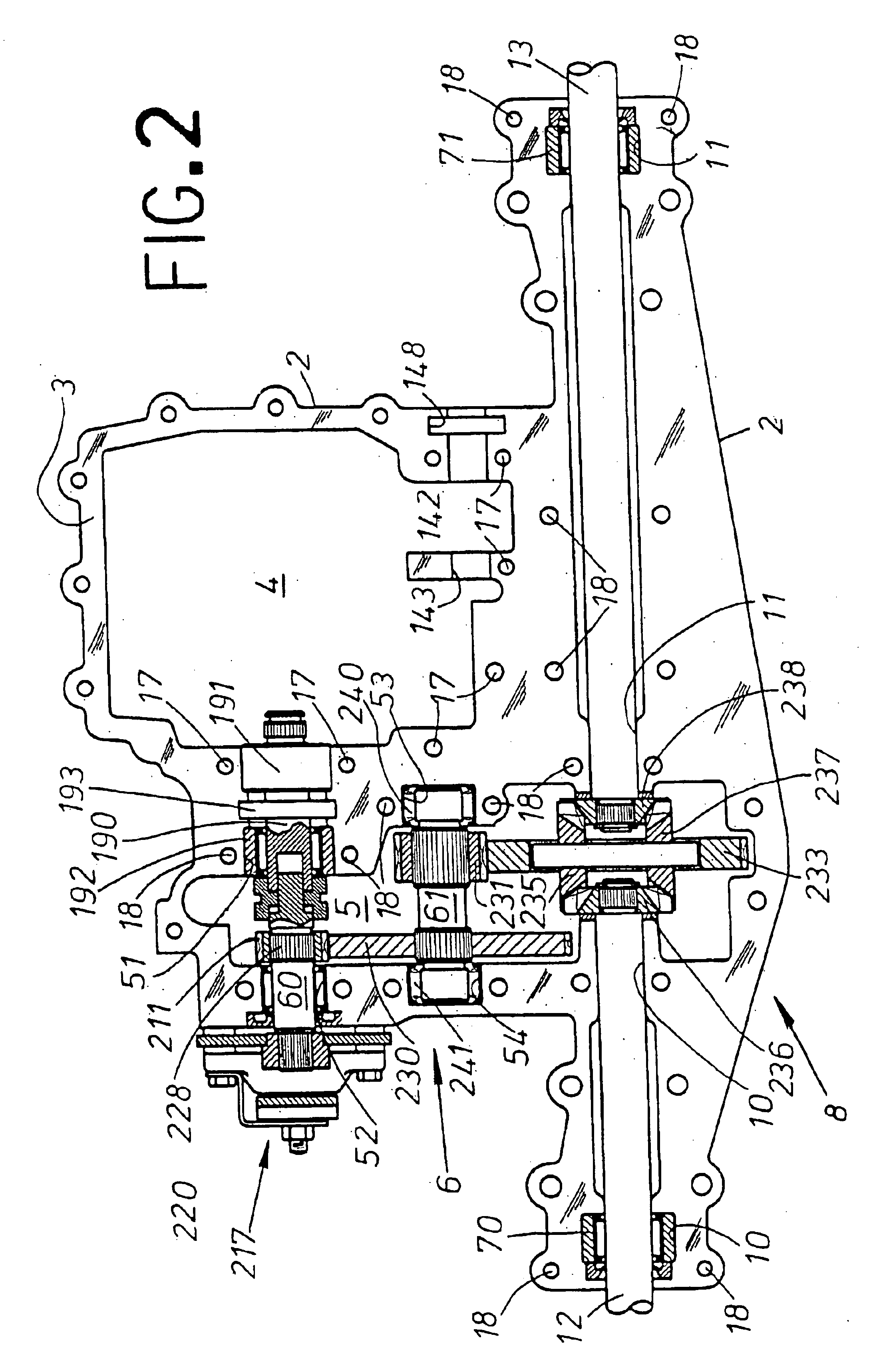
This invention relates to hydrostatic transaxles which are now used in increasing numbers for lawn care and other outdoor duties as the preferred choice for power transmission drive lines in products such as lawn and garden tractors, pedestrian walk-behind mowers and snow blowers.
DESCRIPTION OF THE RELATED ART
Hydrostatic transaxles of the type currently sold in the marketplace require careful assembly and service practices in order to avoid certain problems occurring that may result in lower than expected operational life of the product. Hydrostatic transmissions operate most effectively and efficiently when they are constructed with exceedingly small clearances between their reciprocating and sliding elements. The transmission of power by such hydrostatic transmissions has now become widespread and the attendant small fluid leakage loss from the internal pressurized circuit during operation which is inherent with this type of speed changing device is generally considered insignific...
PUM
 Abstract
Description
Claims
Application Information