Optical router switch array and method for manufacture

a switch array and optical router technology, applied in the field of optical switch arrays, can solve the problems of large device electric power consumption, high maintenance cost, bulky switch array, etc., and achieve the effects of stable versus, simple configuration, and stable operation within the operational spectral region

Inactive Publication Date: 2005-04-26
KENT OPTRONICS
View PDF21 Cites 38 Cited by
  • Summary
  • Abstract
  • Description
  • Claims
  • Application Information

AI Technical Summary

Benefits of technology

[0008]In order to overcome the disadvantages related to the mentioned prior art technologies, the present invention provides a new technology comprising an optical switch array, which is based on a single layer electrically switchable optical mirror, wherein the switchable optical mirror is further created from a holographic device made from cholesteric liquid crystal composite material. The switchable mirror of the present invention is polarization insensitive, stable within the operational spectral region, and stable versus temperature. In addition, the switchable mirror of the present invention is fully integrated and features no-moving parts (as compared to MEMs technology), simple configuration, low insertion loss, low polarization dispersion loss, low cross talk, rigidity, high manufacture capability (as compared the prior art liquid crystal technologies), low power consumption (as compared to air bubble technology), fast switching speed (as compared to thermal technology), and low cost (versus all the mentioned technologies).

Problems solved by technology

These switches are bulky and slow in switching speed.
In addition, their maintenance cost is high.
However, this device consumes significant electric power and its long-term stability as well as environment stability remains questionable.
However, it is difficult to accurately align the optical beams being switched between the input and output ports.
In addition, its long-term lifetime remains questionable because of the mechanical motion of the mirror.
Again, this technology is slow and consumes high power and its thermal stability remains a question.
Due to the fact that six optical elements (two beam splitters, two LC modulators and two mirrors) are involved in accomplishing one switching action, this switch exhibits a significant insertion loss.
In addition, the switch is bulky and difficult for manufacturing.
Besides, this technology has the same beam alignment problem as in MEMs technology.
Finally, since this technology intrinsically depends on polarization of the light, its polarization dispersion loss is significant.

Method used


Image

  • Optical router switch array and method for manufacture
  • Optical router switch array and method for manufacture
  • Optical router switch array and method for manufacture

Examples


first embodiment

(First Embodiment) Switchable Mirror

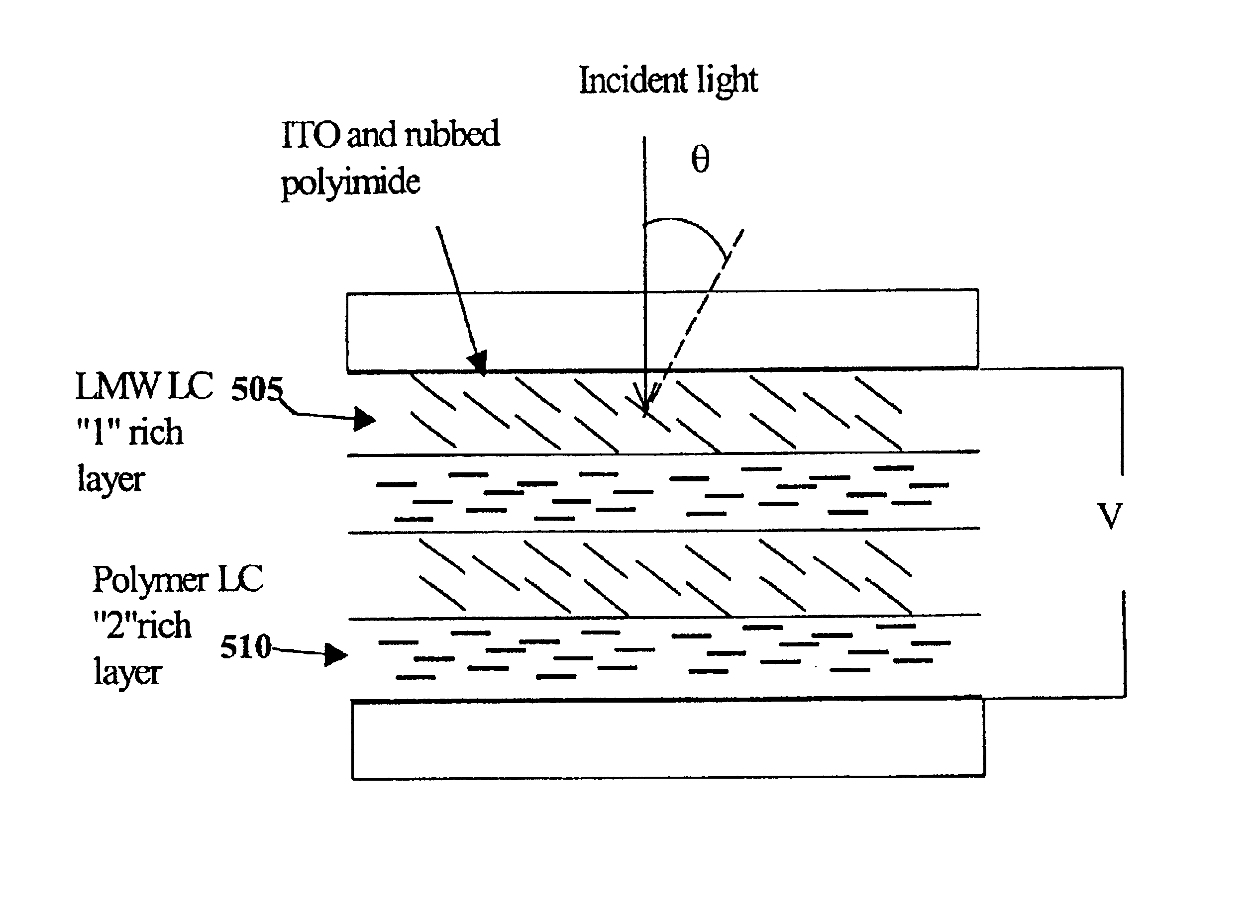
[0057]FIG. 5 illustrates the first embodiment of the present invention of creating a holographically formed switchable mirror from liquid crystal in a nematic phase whose reflection peak is tunable via varying the strength of the applied electric field across the device.

[0058]At zero voltage, both LMW liquid crystal (LC) 505 and liquid crystal polymer 510 are aligned in homogeneous texture. The LMW also containes Indiom-Tin-Oxide ITO and rubbed polymide. Assume that nlce≠npe and nlco=npo. The p-polarization incident light “sees” a Bragg grating with a period 2(nlce+npe).d and is reflected. The S-polarization is passed. However, when voltage is applied, the LMW is re-oriented to have a tilt angle φ. As a result, the P-polarization incident light “sees” an effective refractive liquid crystal index ne|eff which is in between nlce and nlco, i.e., nlce>ne|eff>nlco. Then the device still reflects p-polarization but at a shifted wavelength 2(ne|eff+np)....

second embodiment

(Second Embodiment)

[0059]FIG. 6 illustrates the second embodiment of the invention in which the switchable mirror is made from liquid crystals in cholesteric phase under holographic condition. Similar to the first embodiment, the reflection wavelength of this device is electrically tunable. However, different from the first embodiment, this tunable reflection peak is polarization insensitive. The device has a Bragg grating structure consisting of two sets of alternatively spaced CLC planes 600, 605. The two CLC's have the same selective reflection wavelength at λ1=λ2, the same an average refractive index na1=na2, and the same birefringence Δn1=Δn2. It is further assumed that one CLC is polymerized into a solid state while the other one is LMW CLC that can be electrically switched. The LMC CLC contains ITO and rubbed polymide. ITO is the electric conductive coating that is optically transparent. The rubbed polyimide is used for liquid crystal alignment. The longer axis of the liquid ...

third embodiment

(Third Embodiment) Optical Switch Array

[0069]FIG. 11 shows a schematic of the desired switch array configuration according to the present invention, where an 8×8 switch is illustrated as an example. It should be noted that although there may be an alternative arrangement for the mirror elements, however, the spirit using the single layer switchable mirror to build the switch array remains the same.

[0070]The switch array 1100 is made from switchable mirror elements which are further made from holographic cholesteric liquid crystal. The mirror elements are sandwiched between solid substrates 1120 (e.g., glass and / or plates) and are electrically isolated from each other by using pixilated conductive electrodes, such as Indium-Tin-Oxide (ITO). Each mirror element is independently addressed in a similar way used in liquid crystal display. In order to avoid the beam alignment problem such as that encountered with MEMs technology, the following fabrication method is invented.

[0071]FIG. 12 ...


PUM

PropertyMeasurementUnit
reflectivityaaaaaaaaaa
gap thicknessaaaaaaaaaa
incident anglesaaaaaaaaaa

Abstract

An optical router switch array includes a plurality of switchable mirror elements having holographic liquid crystal arranged in stack cells. Each of the mirror elements is isolated electrically from the other switchable mirror elements by a plurality of substrates alternative arranged between the switchable mirror elements. Holographic gratings are formed on the holographic liquid crystal by exposure to holography at predetermined incident angles. A single switchable mirror element can also be provided in cases where an array is not required. The switchable mirror elements are polarization insensitive, stable within the operational spectral region, and stable versus temperature. The invention also includes methods for manufacturing a single switchable mirror element and the optical arrray.

Description

[0001]This application claims priority from U.S. provisional application 60 / 236,994 filed Sep. 29, 2000.BACKGROUND OF THE INVENTION[0002]1. Field of the Invention[0003]The present invention relates to an optical switch array made from single layer electrically switchable mirror that is made from holographic cholesteric liquid crystal and is polarization independent.[0004]2. Description of the Related Art[0005]Today's fast growing optical telecommunication technology requires sophisticated optical switch and switch array. Currently, electro-mechanical switches are widely deployed in the optical fiber network. These switches are bulky and slow in switching speed. In addition, their maintenance cost is high. Therefore, new technologies are being sought that over perform the electro-mechanical switches. Such a high performance optical switch array should exhibit non-moving parts in a fully integrated form, fast switching speed, low insertion loss, low cross talk, low polarization disper...

Claims


Application Information

Patent Timeline
Patent Type & Authority Patents(United States)
IPC IPC(8): C09K19/02G02F1/1335G02F1/13G02B5/32G02F1/1347G02F1/1333G02F1/137G02F1/29
CPCG02F1/13471G02F1/292G02F1/13718G02F1/133365G02F2203/06G02F2201/307
Inventor LI, LE
Owner KENT OPTRONICS
Why Eureka
Try Eureka