Bipolar electrochemical battery of stacked wafer cells

a technology of bipolar electrochemical batteries and wafer cells, which is applied in the direction of cell components, flat cell groupings, nickel accumulators, etc., can solve the problems of difficult to achieve the proper combination of these characteristics, and the energy storage capacity of the active components of the cell cannot be fully utilized. achieve the effect of improving energy storage capacity, stable and efficient battery performance, and long-term chemical and physical stability

Inactive Publication Date: 2005-05-03
ELECTRO ENERGY
View PDF46 Cites 37 Cited by
  • Summary
  • Abstract
  • Description
  • Claims
  • Application Information

AI Technical Summary

Benefits of technology

[0016]The present invention provides a means for achieving desirable packaging benefits of bipolar construction for multi-cell batteries and of overcoming material and construction problems of some previous approaches. Although the materials of construction for each type of cell are specific to each battery chemistry, the general bipolar construction disclosed herein may be used for many types of electrochemical cells. In particular, several embodiments and examples that follow relate to the rechargeable nickel-metal hydride chemistry but may be generally adaptable to other chemistries.
[0017]An advantage of the present invention relates to providing a bipolar battery construction for primary and/or rechargeable multi-cell batteries that have improved energy...

Problems solved by technology

However, such constructions allocate a large fraction of the multi-cell battery's weight and volume to the packaging and, thus, do not make full use of the energy storage capability of the active components of the cell.
These features are more difficult to achieve in rechargeable batteries due to the charging potential that can accelerate corrosion of the bipolar layer and in alkaline batteries due to the creep nature of the electrolyte.
Achieving the proper combination of these characteristics has proven ...

Method used


Image

  • Bipolar electrochemical battery of stacked wafer cells
  • Bipolar electrochemical battery of stacked wafer cells
  • Bipolar electrochemical battery of stacked wafer cells

Examples


example 1

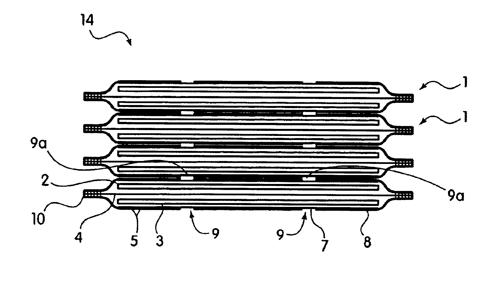
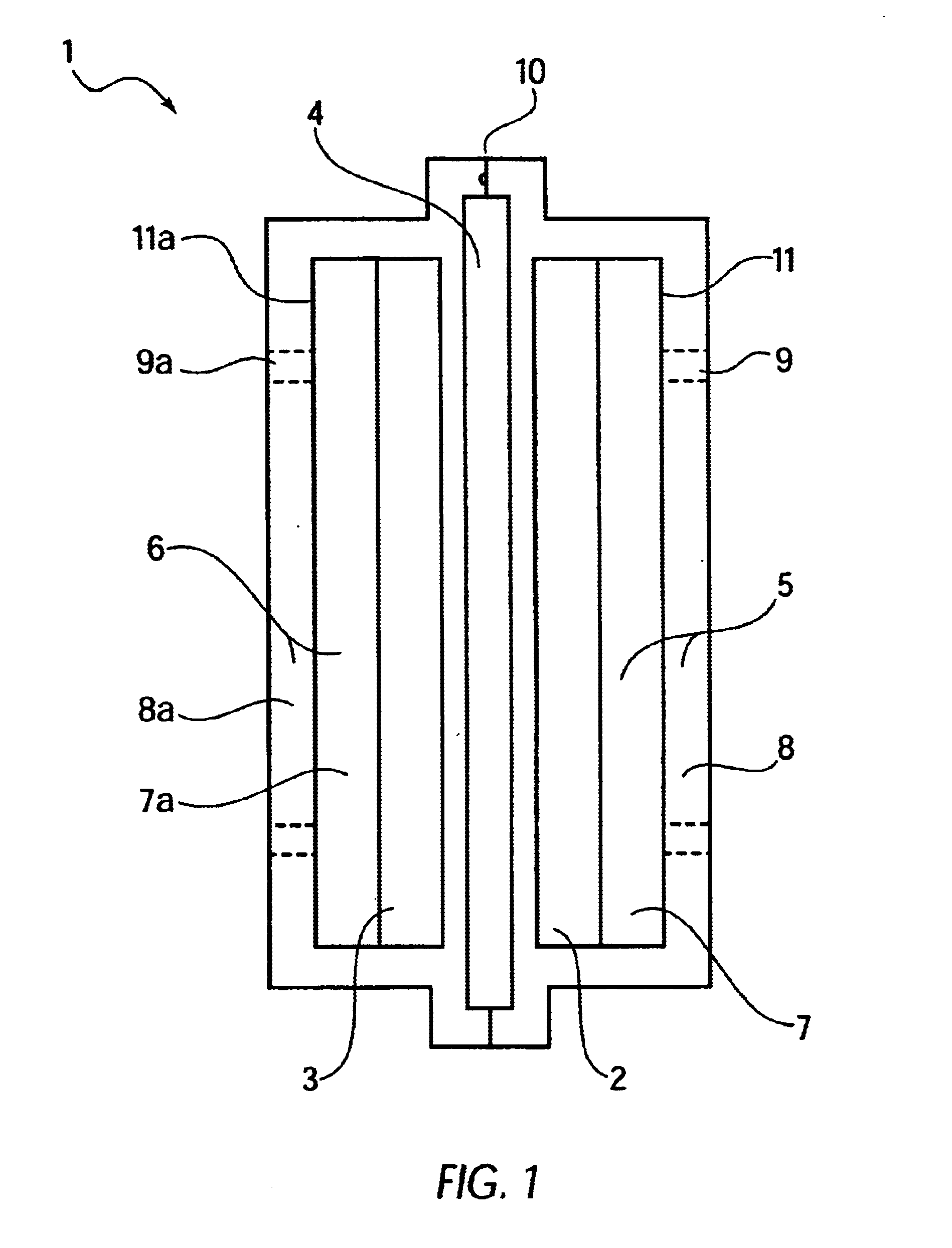
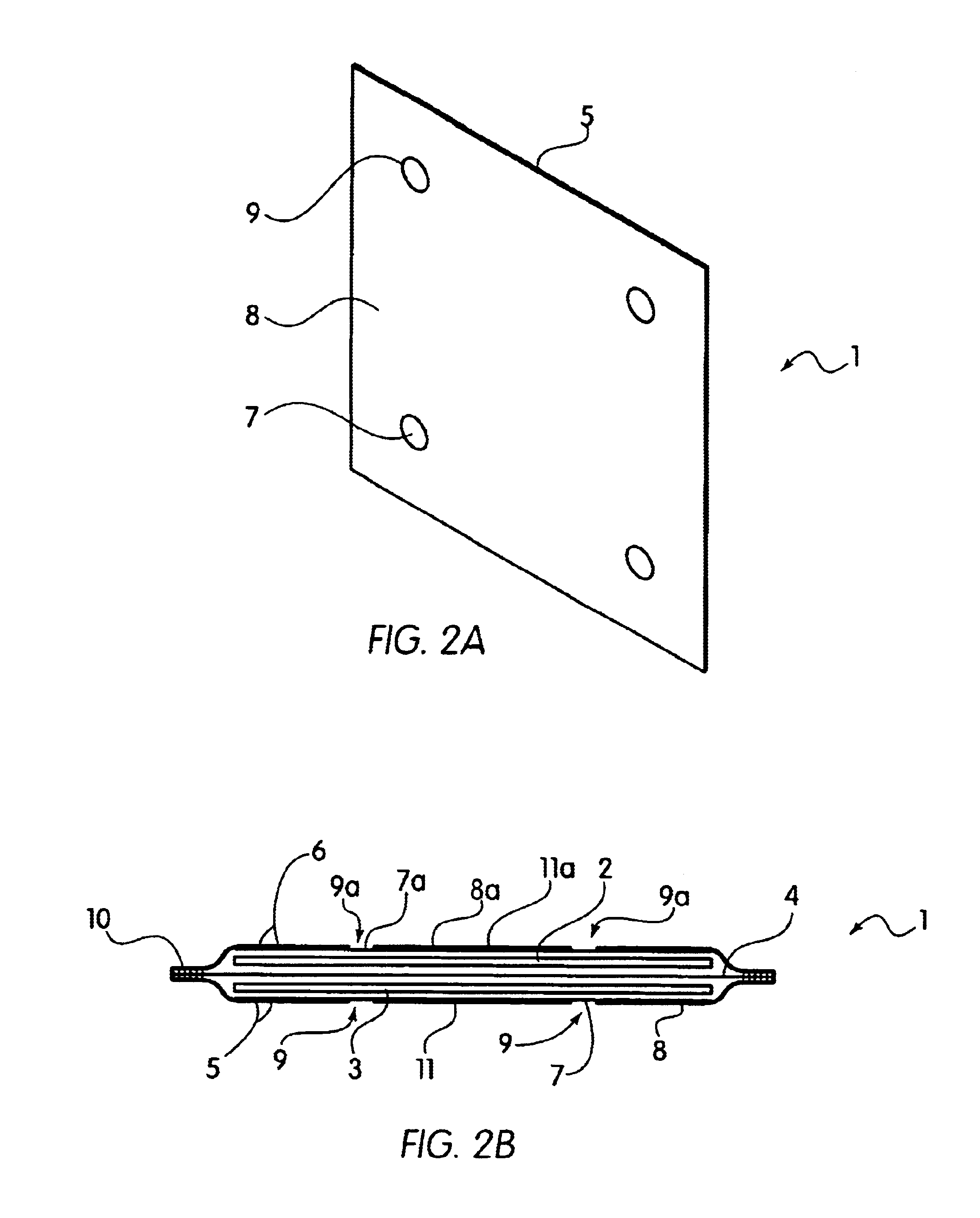
[0073]A single wafer cell including one positive nickel electrode and one negative metal hydride electrode was fabricated in an arrangement as shown in FIG. 1. The electrodes were prepared according to the procedures described in U.S. Pat. No. 5,393,617. In particular, the hydride electrode was prepared by blending a mixture of 45 grams of a Mischmetal hydride alloy, 0.5 grams of PTFE (Teflon®) powder and 4.5 grams of CuO. The Mischmetal hydride alloy used herein was comprised of an alloy of Mn Ni3.5Co0.7Al0.8. The hydride alloy, received as about ⅛ to ¼ inch particle fragmented by dry pressure hydrating five times between vacuum and 200 psi to produce an average particle size of about 50 microns. The mixture was blended in a high speed blender for two 30-second periods. The mixture was then rolled out to a layer approximately 0.060 inch thick, and then folded and rolled to a 0.060 inch thickness in a direction about 90 degrees from the original direction. The above folding and roll...

example 2

[0081]For comparison with the present invention and to demonstrate the advantageous results of the invention, a single cell was constructed as described in Example 1 except that the two sheets of 2 mil nickel foil, 3×3 inch square, of Example 1 were increased to 3¼×3¼ inch square, and the two 3 mil layers of polypropylene film that were 3¼×3¼ inch square were not utilized. The nickel foil sheets were then epoxy bonded directly around the perimeter of the cell. This edge seal served for temporary testing, but may allow electrolyte leakage under endurance testing.

[0082]This cell configuration is not the subject of the present invention because it did not employ Applicant's advantageous laminations 5 and 6, as described herein. However, testing of this cell configuration under the conditions described in Example 1 was useful to demonstrate the advantages of Applicant's present design. In particular, testing demonstrated that the current power capacity of a cell without the outer polyme...

example 3

[0083]In further contrast to the present invention, a cell was assembled and tested as in Example 1 except that the outer layers of the cell were made of a carbon-filled conductive polymeric material of polyvinyl chloride (pvc) nominally 4 mils thick and the outer edges of the cell were heat sealed to a non-conductive polymeric material of pvc to form the edge seal, as described in U.S. Pat. No. 5,393,617. Accordingly, Applicant's laminations of metallic foil / perforated polymeric layer were not employed.

[0084]This example demonstrated the less effective high rate current capabilities of the carbon-filled conductive outer film, as compared to that of Applicant's invention including its advantageous laminations. In particular, FIG. 7 shows the voltage current characteristics of this cell. A comparison of FIGS. 5 (re: Example 1) and 7 demonstrates that the present invention has a higher rate capability.


PUM

PropertyMeasurementUnit
Thicknessaaaaaaaaaa
Thicknessaaaaaaaaaa
Electrical conductoraaaaaaaaaa

Abstract

The bipolar electrochemical battery of the invention comprises:
    • a stack of at least two electrochemical cells electrically arranged in series with the positive face of each cell contacting the negative face of an adjacent cell, wherein each of the cells comprises
    • (a) a negative electrode;
    • (b) a positive electrode;
    • (c) a separator between the electrodes, wherein the separator includes an electrolyte;
    • (d) a first electrically conductive lamination comprising a first inner metal layer and a first polymeric outer layer, said first polymeric outer layer having at least one perforation therein to expose the first inner metal layer, said first electrically conductive lamination being in electrical contact with the outer face of the negative electrode; and
    • (e) a second electrically conductive lamination comprising a second inner metal layer and a second polymeric outer layer, said second polymeric outer layer having at least one perforation therein to expose the second inner metal layer, said second electrically conductive lamination being in electrical contact with the outer face of the positive electrode; wherein the first and second laminations are sealed peripherally to each other to form an enclosure including the electrodes, the separator and the electrolyte.

Description

RELATED APPLICATION(S)[0007]This application is a continuation of patent application Ser. No. 09 / 902,871, filed Jul. 11, 2001, now U.S. Pat. No. 6,503,658.[0008]This invention was made with Government support under contract NAS3-27787 awarded by the National Aeronautic and Space Administration. The Government has certain rights in this invention.FIELD OF INVENTION[0009]The present invention relates generally to packaging methods and fabrication techniques for making electrochemical cells and multi-cell batteries. In particular, the invention relates to electrochemical cell constructions useful for primary and rechargeable bipolar battery structures that have a high energy storage capacity and efficient battery performance. More specifically, this invention relates to electrochemical cells including positive and negative electrode structures and methods of making such cells that are capable of being stacked in a multi-cell battery construction.BACKGROUND OF THE INVENTION[0010]Multi-c...

Claims


Application Information

Patent Timeline
IPC IPC(8): H01M6/48H01M10/04H01M6/42H01M10/34H01M2/02H01M4/66H01M4/00H01M8/02H01M10/00H01M10/0585H01M10/30H01M10/38H01M50/103H01M50/119H01M50/121H01M50/124H01M50/51H01M50/528
CPCH01M2/0275H01M2/202H01M4/667H01M6/46H01M6/48H01M10/0418H01M2/0267H01M2/0207Y10T29/49112H01M2/0287H01M6/42H01M10/0585H01M10/345Y10T29/4911Y10T29/49108Y02E60/10H01M50/124Y02P70/50H01M50/103H01M50/121H01M50/51H01M50/119H01M10/18
Inventor KLEIN, MARTIN G.RALSTON, PAULAPLIVELICH, ROBERT
Owner ELECTRO ENERGY
Why Eureka
Try Eureka