
Porous hollow fiber membranes and method of making the same

a technology of hollow fiber and membrane, which is applied in the field of porous hollow fiber membrane, can solve the problems of inability to achieve the purification level of impounded water, low separation precision, and unreliable sanitation of existing waterworks facilities equipped with flocculating pools in combination with sand filtering pools, etc., and achieves excellent filtering performance, low cost of preparing water, and excellent water quality.

Inactive Publication Date: 2005-05-10
KURARAY CO LTD
View PDF12 Cites 69 Cited by
  • Summary
  • Abstract
  • Description
  • Claims
  • Application Information

AI Technical Summary

Benefits of technology

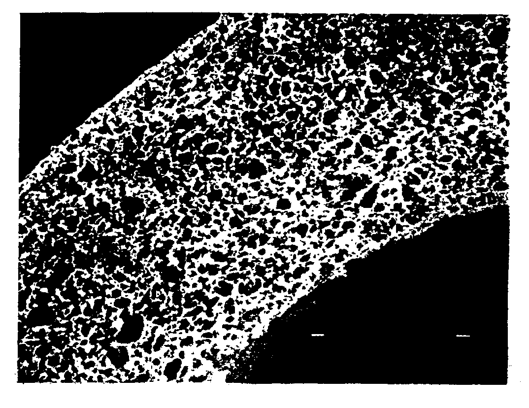
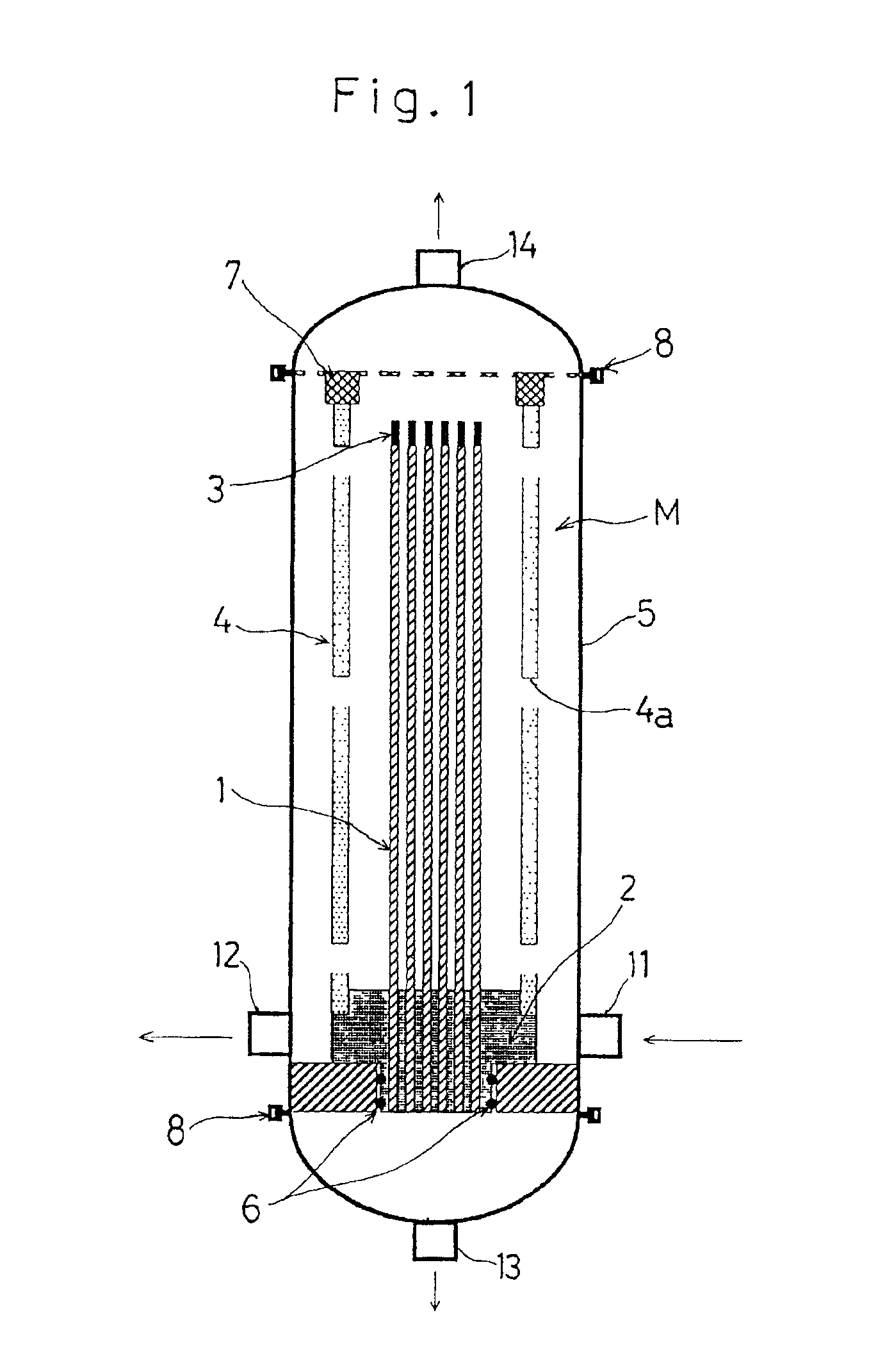
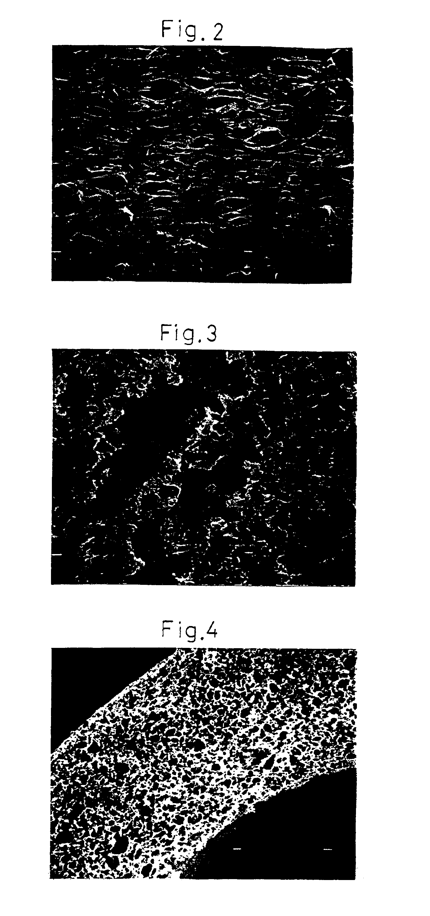
[0020]Accordingly, the present invention has been devised in view of the problems and inconveniences discussed hereinabove and is intended to provide a porous hollow fiber membrane and a method of making the same, in which the filtering performance is excellent, the cost for preparing water is low, application to the use where the sand filtration or the like has been employed in view of the cost can easily be achieved, and the excellent quality of water that is superior to that obtained by the sand filtration in terms of the water quality and the safety factor can be prepared consistently and stably, although not for intended for use in dezymotization such as achieved with the standard hollow fiber membranes.
[0023]With this structure, by using the porous hollow fiber membranes having a particle cutoff within the range of 1 to 10 μm and the pure water permeate flow equal to or higher than 30,000 L / m2 / hr / 100 kPa, any possible reduction in flow rate resulting from clogging can be suppressed markedly and a high filtering flow can be attained and maintained.

Problems solved by technology

The existing waterworks facilities equipped with the flocculating pool in combination with a sand filtering pool have now come to be unreliable in terms of sanitation.
Accordingly, with the conventional physical separating technique such as, for example, the sand filtration, filtration with a filter aid, coagulation and sedimentation or pressurized floatation it often occur that the required purification level of the impounded water cannot be attained.
Also, the sand filtration, the coagulation and sedimentation or the pressurized floatation has a problem in that the separation precision is not smaller than 10 μm and no suspended microparticles of a size greater than it is difficult to remove.
Although the filtration with a filter aid is a process in which a pre-coating layer of the filter aid such as diatomite is formed on a filtering surface such as a filtering cloth and filtration is effected through this pre-coating layer, complicated procedures are required to introduce the filter aid into the pre-coating layer and the untreated water and to replace the filter aid and, moreover, the filter aid itself constitutes a waste to be disposed.
Accordingly, the filtration with the filter aid has a problem in that disposal of the filter aid would eventually lead to environmental pollution.
On the other hand, if attempt is made to purify the impounded water using a biological oxidizing process, a relatively long time is required to purify, the untreated water and a relatively large space for installation is required to compensate for it.
There are other problems such as complicated maintenance, management and requirement of an apparatus for removing suspended matter after the treatment.
However, according to the technique disclosed in this Japanese Laid-open Patent Publication No. 59-206091, since the filtering speed is so low that treatment of a large quantity of impounded water such as water for a swimming pool requires the use of an equipment having a large membrane area and, therefore, this known technique is impractical because of the cost incurred in preparing the equipment and the high running cost.
However, with this method, if the proportion of the amount of filtration through the hollow fiber membranes relative to the entire amount of the impounded water is low, the water quality cannot be improved and, conversely, if the proportion of the amount of filtration through the hollow fiber membranes relative to the entire amount of the impounded water is increased, the water quality may be improved, but a problem associated with the increased cost for the equipments would occur and, therefore, no satisfactory result cannot be necessarily obtained.

Method used


Image

  • Porous hollow fiber membranes and method of making the same
  • Porous hollow fiber membranes and method of making the same
  • Porous hollow fiber membranes and method of making the same

Examples


example 1

[0085]A spinning dope 20 wt % of polysulfone (UDEL-P1800, manufactured by and available from AMOCO Japan, Ltd. Hereinafter, this particular polysulfone is referred to as PSf.), 6 wt % of ethylene glycol (hereinafter referred to as EG), 18 wt % of silicon oxide having an average particle size of 4.5 μm, and 54 wt % of N, N-dimethyl acetamide (hereinafter referred to as DMAc) was prepared by the following procedure. Specifically, after EG has been dissolved into DMAc, the silica powder was uniformly dispersed in the DMAc solution by the use of a home jettor to provide a dispersed liquid which was subsequently added with PSf. The resultant mixture was then stirred for 8 hours at 60° C. to thereby dissolve the PSf, resulting in the white-colored slurry in which the silicon oxide was uniformly dispersed. This slurry was used as the spinning dope.

[0086]The spinning dope obtained in the manner described above was thereafter degassed. While the degassed spinning dope was maintained at 50° C...

example 2

[0089]In a manner similar to that in Example 1, except that the use was made of the spinning dope containing 20 wt % of PSf, 6 wt % of EG, 20 wt % of silicon oxide having an average particle size of 11 μm, 2 wt % of silicon oxide having an average particle size of 4.5 μm and 52 wt % of DMAc, the hollow fiber membranes were manufactured. The resultant hollow fiber membranes were found to have a pure water permeate flow of 520,000 L / m2 / hr / 100 kPa and a particle cutoff of 5.0 μm.

example 3

[0090]In a manner similar to that in Example 1, except that the use was made of the spinning dope containing 20 wt % of PSf, 4 wt % of EG, 14 wt % of silicon oxide having an average particle size of 1.5 μm, and 62 wt % of DMF, the hollow fiber membranes were manufactured. The resultant hollow fiber membranes were found to have a pure water permeate flow of 39,000 L / m2 / hr / 100 kPa and a particle cutoff of 1.2 μm.


PUM

PropertyMeasurementUnit
Temperatureaaaaaaaaaa
Lengthaaaaaaaaaa
Lengthaaaaaaaaaa

Abstract

A porous hollow fiber membrane having a particle cutoff within the range of 1 to 10 μm and a pure water permeate flow equal to or higher than 30,000 L / m2 / hr / 100 kPa. This porous hollow fiber membrane can be prepared by a method including, while a spinning dope containing a base polymer as a material for forming the porous hollow fiber membrane, an additive used for facilitating a phase separation of the spinning dope, a solvent compatible with both the base polymer and the additive and a mass of microparticles insoluble to the compatible solvent and uniformly dispersed in a liquid medium and having an average particle size within the range of 1 to 20 μm, and a coagulating liquid for forming the hollow fiber membrane is used, a step of forming the hollow fiber membrane according to a dry-wet spinning method or a wet spinning method, and a step of extracting and removing the microparticles by immersing the hollow fiber membrane, which has been spun, into an extracting solution effective to dissolve the microparticles, but ineffective to dissolve the base polymer.

Description

BACKGROUND OF THE INVENTION[0001]1. Field of the Invention[0002]The present invention relates to porous hollow fiber membranes for use in filtration of untreated water and a method of making such porous hollow fiber membranes.[0003]2. Description of the Prior Art[0004]In recent years, a filtering technique utilizing filtering membranes having a permselectivity has made a remarkable progress. Those filtering membranes are currently utilized in practice in numerous applications including, for example, production of ultrapure water, preparation of medicines, sterilization and finalization of brewages and purification of drinking water. The use of the filtering membranes has widely circulated to meet with the requirement to refine water (a high degree treatment), improvement in sanitation and improvement in precision. Of the various filtering membranes, the hollow fiber membrane has a feature in that the space for installation per unitary membrane area can be reduced. However, in terms ...

Claims


Application Information

Patent Timeline
IPC IPC(8): B01D67/00B01D63/02B01D69/02B01D71/00B01D69/00B01D69/08B01D71/68C02F1/44D01F6/02D01D5/247D01F6/26D01D5/00D01D5/24
CPCB01D63/024B01D67/003B01D69/02B01D69/08B01D71/68C02F1/444D01D5/24D01D5/247D01F6/26B01D63/021B01D67/0011B01D2313/90B01D2323/08B01D2323/12B01D2323/30B01D2325/20B01D2325/36
Inventor KOMATSU, KENSAKUKAWATA, ICHIROUISHII, SHIGENOBUSATO, YOSHIONAKAHARA, SEIICHI
Owner KURARAY CO LTD
Learn More