Structure and method for manufacturing compact optical power monitors of highly reliable performance

a technology of optical power monitors and manufacturing methods, applied in the direction of optical apparatus testing, instruments, optical radiation measurement, etc., can solve the problems of insufficient compactness, versatility and reliability of sensors and monitors, troubleshooting of optical systems, etc., to simplify and reliable configuration, simplify manufacturing processes, and reduce insertion loss

Inactive Publication Date: 2005-05-17
PACTONIX
View PDF7 Cites 9 Cited by
  • Summary
  • Abstract
  • Description
  • Claims
  • Application Information

AI Technical Summary

Benefits of technology

[0005]It is therefore an object of the present invention to provide a new and improved simplified and reliable configuration and manufacturing method to provide compact and reliable power monitor device such that the above-mentioned difficulties and limitation can be resolved. This invention discloses a method to simplify the manufacture processes by forming the tapping layer as optical splitting / tapping layer directly on the GRIN lens without alignment and assembling processes. Furthermore, the new and improved configuration and manufacture method take advantage of the optical path deviations between incident / reflection beams through a GRIN lens when there is a small linear shift between the optical axes of the fiber pigtail and GRIN lens. More reliable power monitor device with reduced insertion loss can be achieved with new and improved alignment method implemented with a set of holding tubes to achieve minimum insertion loss between the incident and reflective beams.
[0006]Specifically, it is an object of the present invention to provide a simple and reliable device to sample and monitor signals in an optical system. The power monitor is implemented with a filter-centered packaging design to achieve high environmental stability. Integration of the tapping and detection elements is implemented as part of the design to achieve a compact device configuration and to simplify the processes of device manufacture. The new and improved configuration also utilizes concurrent light collecting and focusing functions to improve the signal collection efficiency. The concurrent light collecting and focusing unit is packaged as part of a hermetically sealed sensor housing to provide flexibility of selecting sensors with various degrees of sensitivities and response time. The power-sensing device disclosed in this invention is therefore useful not only for signal intensity detection but also for other broader ranges of applications such as data quality analyses. The new and improved device as disclosed in this invention thus provide several key advantages including but not limited to ultra compactness, broad versatility, long term device dependability and reliability, and design flexibility to fit into wide varieties of existing optical systems. The simplified configuration of the device as disclosed in this invention further streamline the manufacturing processes and reduce the production cost of the power sensing devices.

Problems solved by technology

A technical challenge is faced by those of ordinary skill in the art of designing and manufacturing optical devices to provide compact and reliable optical sensing and monitoring devices including power monitors with application versatility that can be conveniently implemented in different optical systems to carry out the self monitoring and diagnostic functions.
Specifically, as the optical network communication systems are more broadly employed to perform signal transmissions with higher bandwidths while various optical systems are becoming more complicate, the maintenance and trouble shooting of the optical systems become more difficult.
Conventional techniques of optical sensing and monitoring devices are not able to provide the sensors and monitors with sufficient compactness, versatility and reliability, including the optical power monitors, suitable for such applications.

Method used


Image

  • Structure and method for manufacturing compact optical power monitors of highly reliable performance
  • Structure and method for manufacturing compact optical power monitors of highly reliable performance
  • Structure and method for manufacturing compact optical power monitors of highly reliable performance

Examples


Embodiment Construction

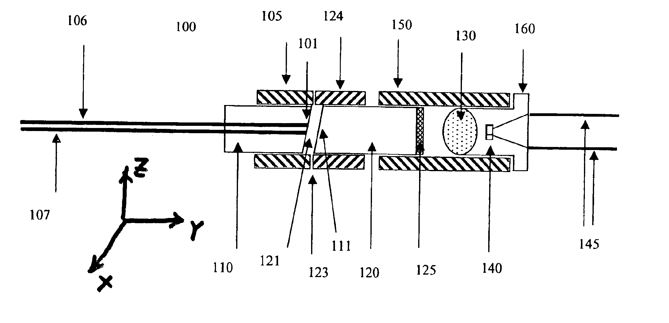
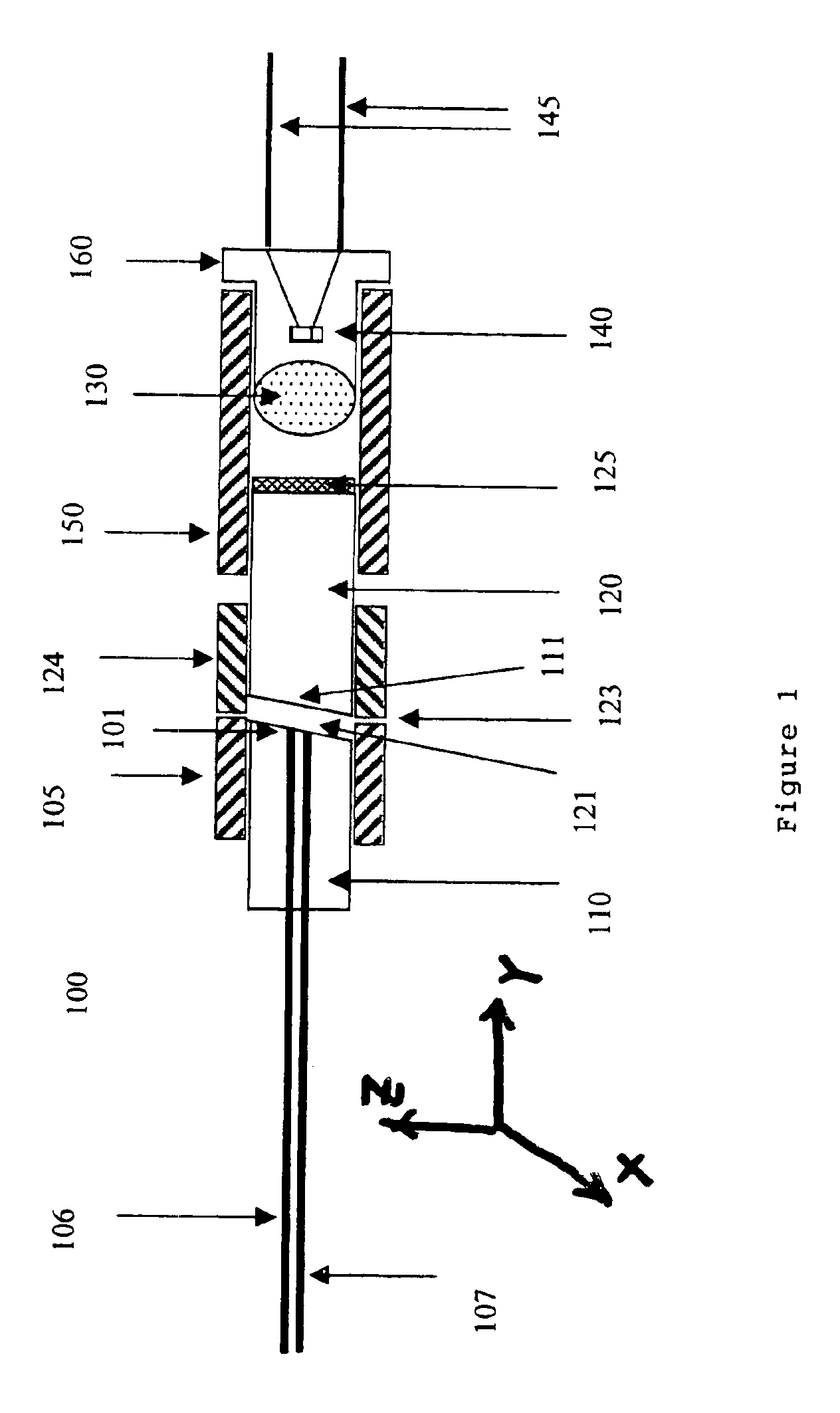
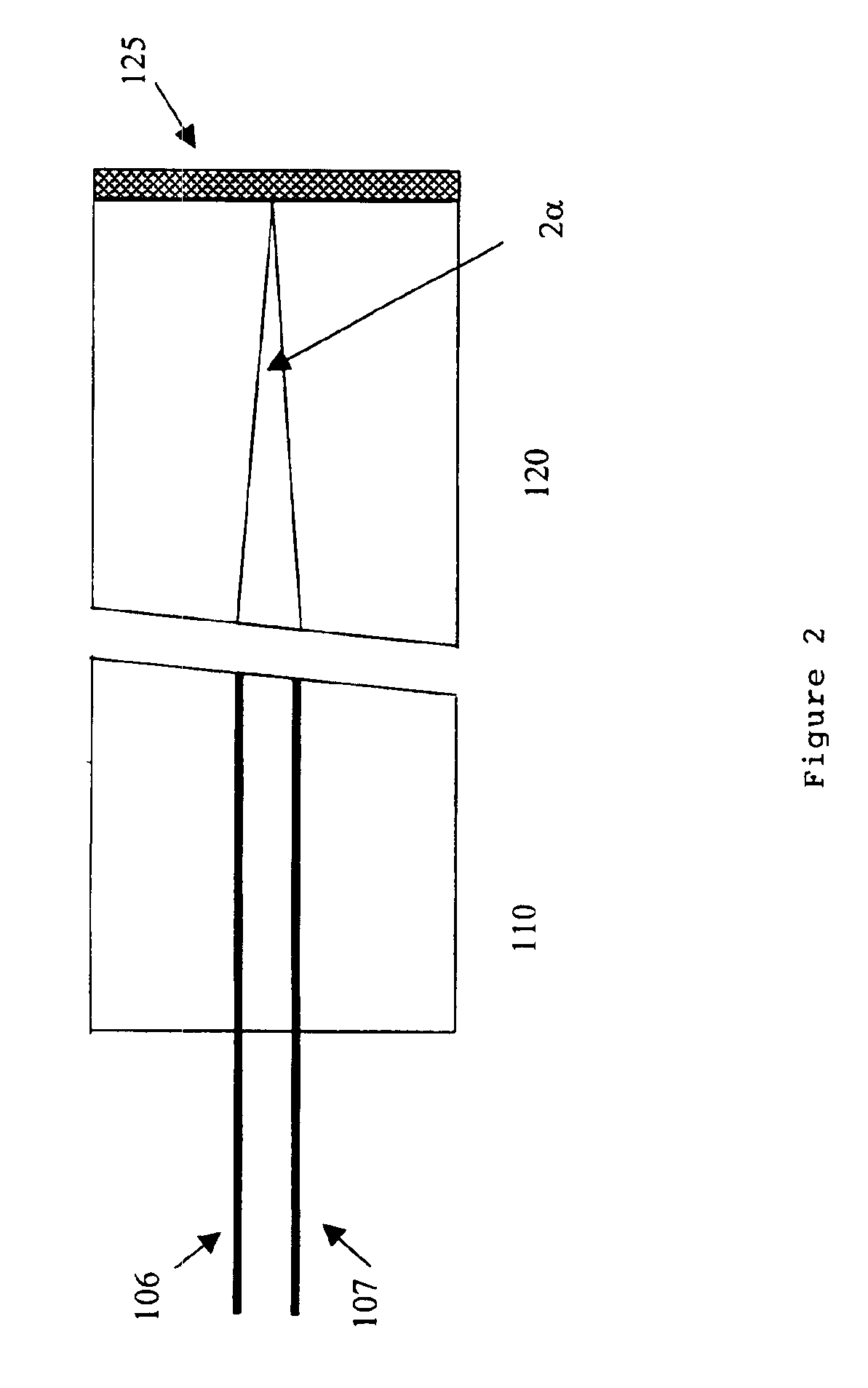
[0013]Referring to FIG. 1 for a preferred embodiment of an optical power monitor 100 of this invention. The improved power monitor 100 includes a dual fiber ferrule 110 to receive an input beam from an input optical fiber 106 and projecting an output beam from an output optical fiber 107. The input beam received from the input optical fiber 106 is projected into a beam collimator 120, e.g., a GRIN lens 120 coated with a filter coating 125. The filter coating 125 functions as a beam splitting-taping filter to transmit a tapped portion of the beam through a focus lens 130 onto a photo-detector, e.g., a photodiode 140 for measuring the intensity of the beam received form the input optical fiber 106. The splitting-tapping filter 125 further reflect a major portion of the beam back through the GRIN lens 120 onto the output optical fiber 107 as an output optical beam. The splitting-tapping filter 125 is formed as a multiple-layered coating deposited onto the focusing surface of the GRIN l...


PUM


Abstract

A new low-cost, highly reliable and compact optical power monitor is manufactured with simplified structure and improved configurations that require only lateral position adjustment for input / output beam alignment. A compact size is achieved by employing prefabricated housing containing a highly effective focus lens placed at fixed position relative to an optical sensor, e.g., a photodiode. The prefabricated housing further function as a seal housing for direct plugging into a holding tube fitting seamlessly to a GRIN lens to focus the tapped collimated beam to the photo sensor thus greatly simplify the manufacturing processes without alignment requirements. Thermal stability and reliable performance is achieved by applying multiple-layered optical reflection-transmission coating directly onto the end surface of a GRIN lens for tapping a small portion of the collimated beam onto the focus lens and the photo sensor. The insertion loss can be conveniently minimized by laterally shifting the relative position of a dual fiber ferrule and the GRIN lens without complicate angular adjustments. A power monitor with compact size, high damage threshold, low manufacture cost and high performance stability is provided for convenient implementation in new and existing optical systems.

Description

[0001]This Formal Application claims a Priority Date of Mar. 15, 2002 benefited from a Provisional Application 60 / 364,983 filed by the same Applicant of this Application on Mar. 15, 2002.FIELD OF THE INVENTION[0002]This invention relates generally to a device configuration and method for making optical power monitors. More particularly, this invention relates to a simplified device configuration and method for manufacturing optical monitor to provide reliable performance.BACKGROUND OF THE INVENTION[0003]A technical challenge is faced by those of ordinary skill in the art of designing and manufacturing optical devices to provide compact and reliable optical sensing and monitoring devices including power monitors with application versatility that can be conveniently implemented in different optical systems to carry out the self monitoring and diagnostic functions. Specifically, as the optical network communication systems are more broadly employed to perform signal transmissions with ...

Claims


Application Information

Patent Timeline
Patent Type & Authority Patents(United States)
IPC IPC(8): G01J1/42G02B6/42G01J1/02G01M11/00G02B5/08H01L31/0232
CPCG01J1/4257G02B6/4214G02B6/4204G01J1/0204G02B6/4222G02B6/422
Inventor SHI, ZHOUZHENG
Owner PACTONIX
Why Eureka
Try Eureka