Secondary combustion for regeneration of catalyst and incineration of deposits in particle trap of vehicle exhaust

a technology of catalyst and catalyst injection, which is applied in the direction of engine components, machines/engines, mechanical equipment, etc., can solve the problems of catalysts that are most effective, complex engine operation, and inefficient engine operation, and achieve the effect of no power loss

Inactive Publication Date: 2005-05-24
BORGWARNER INC
View PDF6 Cites 37 Cited by
  • Summary
  • Abstract
  • Description
  • Claims
  • Application Information

AI Technical Summary

Benefits of technology

[0012]The relatively high velocity and good swirl and turbulence of gas in the exducer chamber promotes excellent mixing of fuel and air, and the higher temperature and pressure in the exducer chamber, compared with conditions in the tailpipe, promotes efficient burning. Thus, utilizing the turbocharger turbine exducer chamber as a combustion chamber eliminates many of the problems, as well as components, associated with burners located in the tail pipe.
[0015]This auxiliary burner in the turbocharger turbine exducer also brings about an increase in exhaust gas temperature, and can quickly bring the temperature of the catalytic converter up to peak performance range. Thus, following a cold start, the catalytic converter is quickly brought to maximum range, and NOx emissions are maintained low.
[0017]The system is particularly advantageous in that it operates completely independently of engine operation. Thus, there is no switching of the engine from lean to rich operation and back again, no retarding of timing of ignition or injection, no throtteling, no loss of power, and no change in driving or handling characteristics experienced by the driver, and no need to remap engine operation for every engine and exhaust modification.

Problems solved by technology

However, programming engine operation for the required relationship between the lean operating phase and the rich operating phase in the combustion control of the vehicle engine is complex.
Another problem with storage catalytic converters is that in some converters a lean-rich cycle with respectively equal durations of a lean and rich motor operating phases (for example 60 seconds each) is required.
This results in inefficient engine operation.
Yet another problem with catalytic converters is that catalysts are most effective at operating temperatures of 300° to 400°.
During cold start-up of the engine the catalyst is inefficient, NOx emissions are high, and emissions standards may not be met.
At low load conditions or at idle, exhaust temperatures may only reach 200° C. At this low exhaust gas temperature the catalytic converter is cool and ineffective.
It is known to increase exhaust gas temperature by retarding ignition timing in gasoline engines or retarding fuel injection timing in diesel engines (since heat of combustion not converted into mechanical work is vented to the exhaust), but the resulting increase in temperature is limited.
Further, retarding timing reduces engine power, hampering engine operability.
Under typical operating conditions such high exhaust temperatures are not experienced for sufficient time periods to clear the trap.
Thus, particulates accumulate and and eventually the trap becomes plugged, increasing backpressure.
However, it is difficult to maintain stable combustion at low pressures.
Further, these systems suffer from disadvantages associated with cost, safety and durability.
With a limited explosive containment rating, the danger of locating such a thin walled burner near a vehicle fuel tank is readily apparent.
Further, parking a vehicle with a hot burner in the exhaust pipe on a flammable surface such as dry grass is dangerous.

Method used


Image

  • Secondary combustion for regeneration of catalyst and incineration of deposits in particle trap of vehicle exhaust
  • Secondary combustion for regeneration of catalyst and incineration of deposits in particle trap of vehicle exhaust

Examples


Embodiment Construction

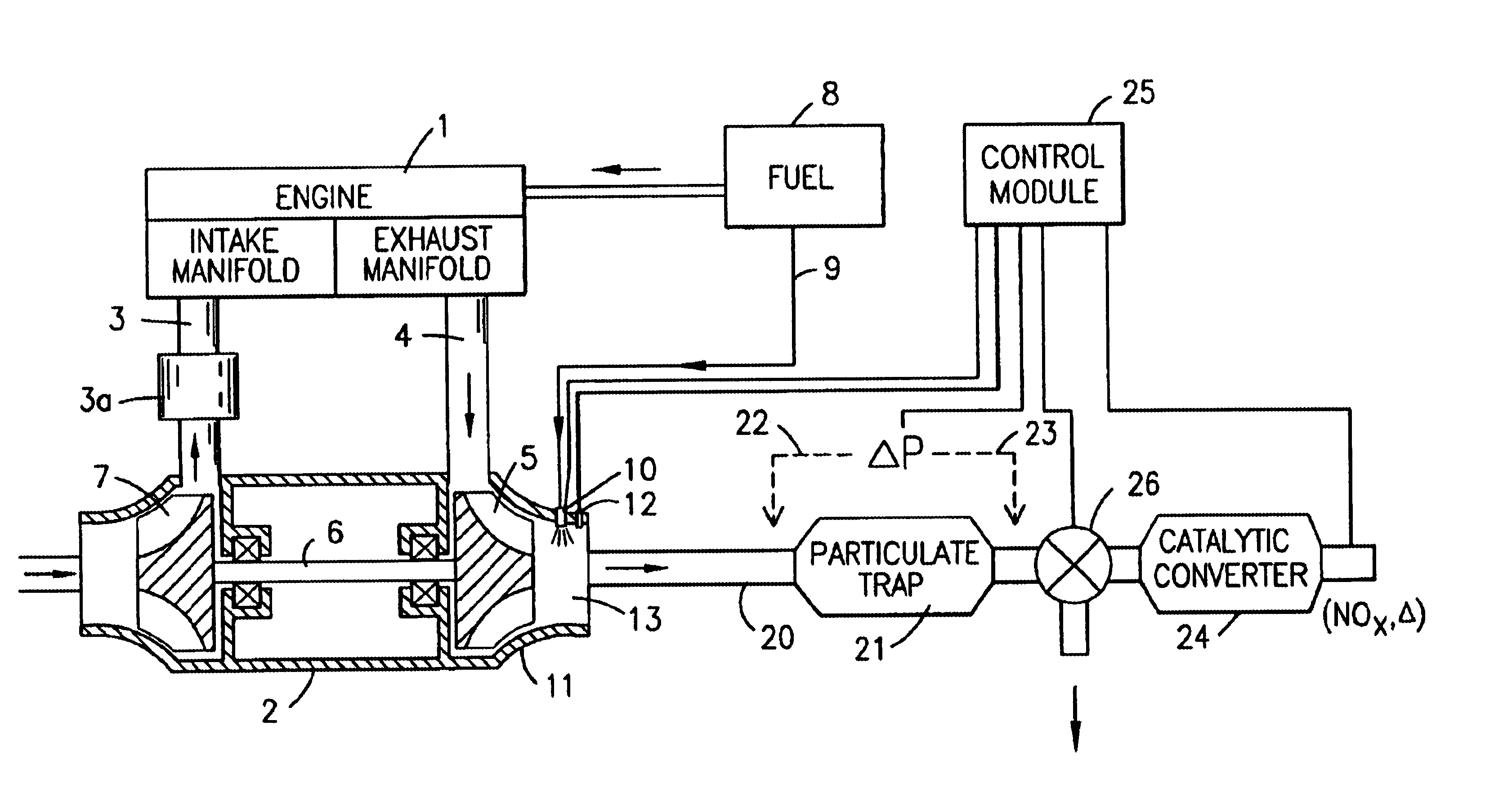
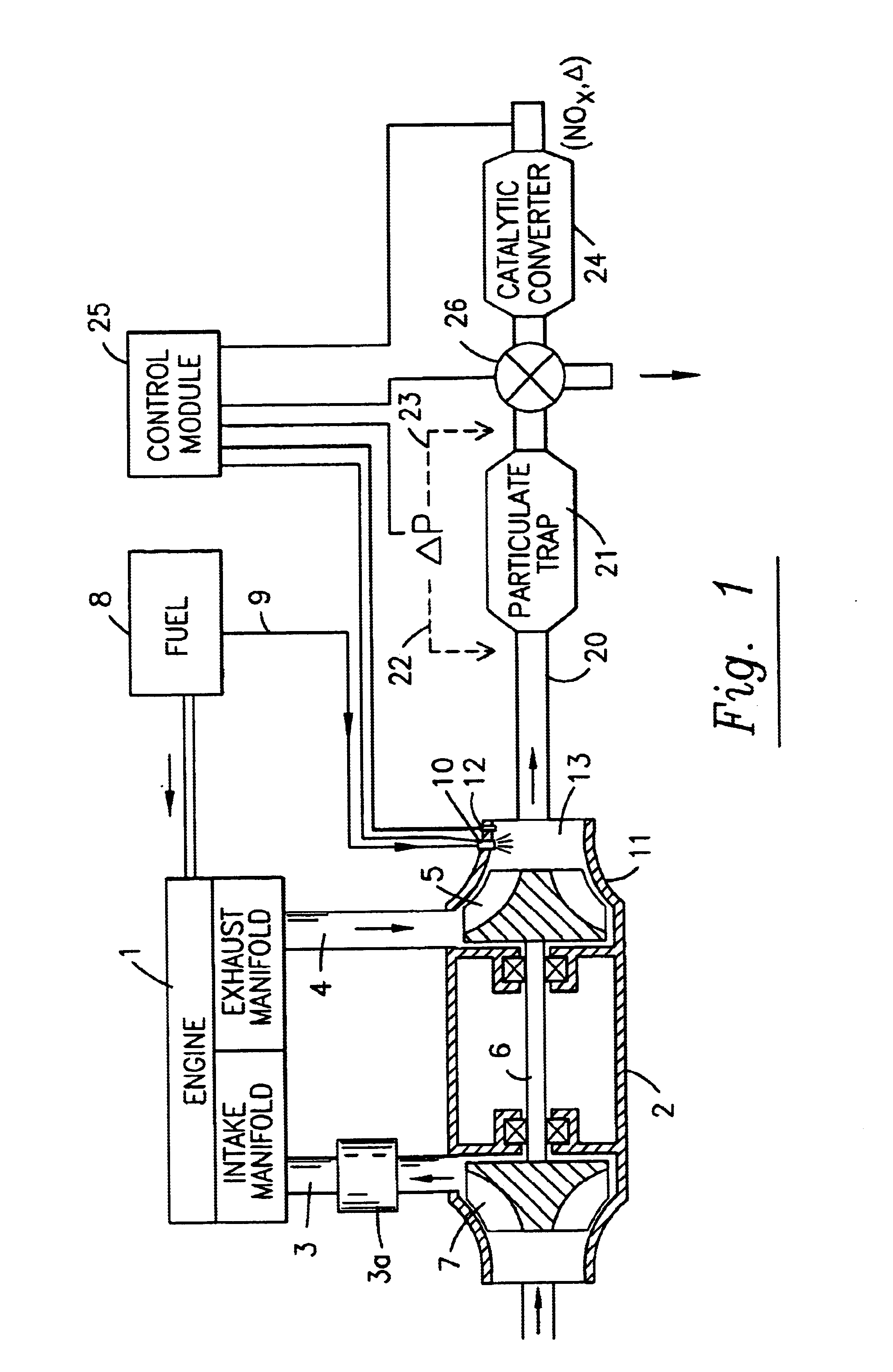
[0020]The system and device for regeneration of catalyst and incineration of deposits in the particle trap of a vehichle exhaust of the present invention is illustrated in FIG. 1.

[0021]The engine 1 is in fluid communication with a turbocharger 2 via charge air intake manifold 3 and exhaust manifold 4. Exhaust gas discharged from an internal combustion engine 1 drives a turbine wheel 5 to a relatively high rotational speed (e.g., 190,000 RPM). The turbine wheel is located within a turbine housing and is mounted on one end of a shaft 6. A compressor impeller 7 is mounted on the other end of the shaft, and is driven by the turbine wheel to compress air. Since the temperature of the compressed air is elevated, charge air from the compressor may be cooled by intercooler 3a, lowering the temperature and / or increasing air density. This cooled compressed air is then communicated to the engine, thereby supplying charge air to the engine for increasing engine performance.

[0022]Fuel from fuel ...


PUM


Abstract

A system and device for providing secondary combustion for regeneration of catalyst in a catalytic converter (24) and / or for regeneration of a particulate trap (21) is provided. The secondary combustion takes place in the exducer chamber (13) of a turbine of a turbocharger (2), and generates heat for bringing a catalyst up to peak oxidation or reduction temperature, for regeneration of a catalyst, and incineration of particulates in a trap. The system takes advantage of heat and turbulence in the exducer chamber for promoting fuel / air mixture and for simplifying the amount of parts needed to incorporate a secondary combustion means into a turbocharger equipped primary combustion system (1).

Description

FIELD OF THE INVENTION[0001]The present invention concerns a system and device for secondary combustion in a vehicle exhaust, useful for generating heat for regeneration of catalyst and / or incineration of deposits in the particle trap. The system and device are capable of being operated completely independently of engine operation, and are particularly suitable for turbocharged diesel powered vehicles.BACKGROUND OF THE INVENTION[0002]The combustion of fuel in a diesel or Otto engine results in production of various pollutants such as heavy hydrocarbon particles, carbon monoxide, nitrogen oxides (NOx) and carbonaceous particulate matter. Emissions control requirements mandate low levels of emissions.[0003]Among exhaust gas cleaning systems, NOx storage catalytic converters are well known. This type of catalytic converter is comprised of two material components. The first serves for adsorbing and storing NOx during lean operation of the engine. Lean operation is when the combustion ai...

Claims


Application Information

Patent Timeline
Patent Type & Authority Patents(United States)
IPC IPC(8): F01N3/023F01N3/025F01N3/035F02B37/20F02B37/12
CPCF01N3/0253F01N3/0256F02B37/20F01N3/035Y02T10/144Y02T10/12
Inventor ROBY, STEVE
Owner BORGWARNER INC
Why Eureka
Try Eureka